


Senior Editor
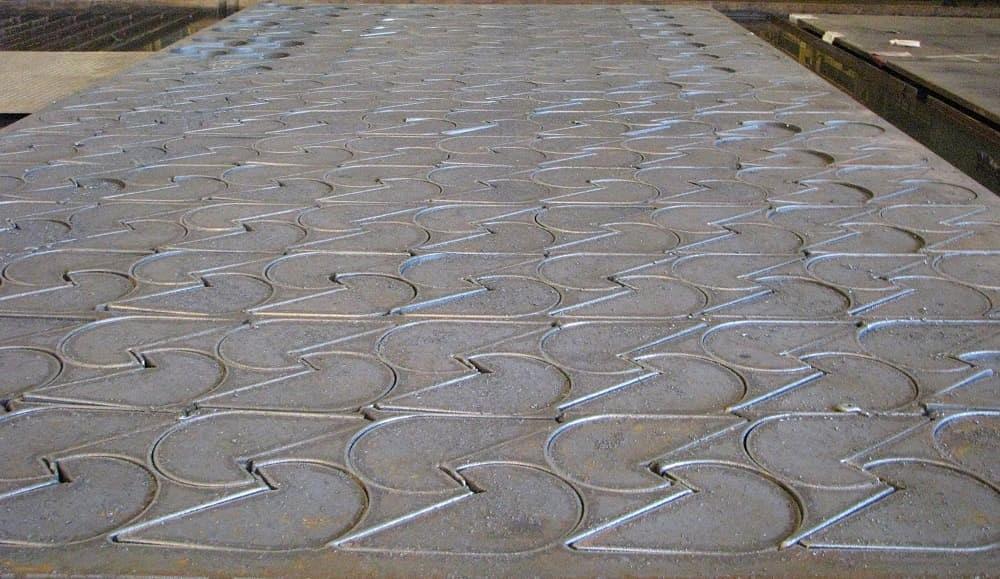
Artificial intelligence helps metal fabricators get more out of the two primary cost drivers in any fab shop: time and material. Photo provided
Metal fabricators know what it’s like to scramble for time, an odd situation when you consider just how quickly modern lasers cut and press brakes bend. Why do fabricators scramble, exactly?
The root causes will depend on a shop’s situation, of course. Bob Jencks, the founder of CAD/CAM provider PEP Technology, sees one of those root causes happening when technicians sit all day in front of computer screens, correcting and manually redrawing part files for nesting.
Problem is, interpreting and correcting all those drawings isn’t easy and can take serious time. Deep interpretation that factors in all the variables—including all the other jobs being routed through the shop—is simply outright impossible for people to do manually for every cutting program. This is why software and artificial intelligence are playing an increasing role.
“Most shops employ a person that manually spends the day cleaning up drawings,” Jencks said. “People shouldn’t spend their days doing that. It’s a waste of valuable resources, and we can now eliminate that waste.”
Why are shops employing people to clean up drawings? Much of it has to do with the ellipse and spline data in 2D and 3D CAD files, as well as PDFs that have to be redrawn.
Jencks pointed to a contoured, rough edge. It looks as if, instead of a smooth arc, the machine tried to cut a series of short, straight lines—and that’s exactly what it was doing. The software exported the curve as a series of short lines, which causes the cutting head to move inefficiently through the contour, adding heat to the part.
“In some cases, the machine will lose the cut, and in other cases the edge will just look horrible,” Jencks said. “And typically, the cutting machine operator can’t see these errors in the program.” To maintain quality, “the machine operator will cut all jobs at the slower cutting speed needed to cut the short consecutive lines.” If that curve had been converted to a tangent arc, the head would have moved smoothly through the contour.
Next comes the common-line-cutting and material yield variables. Jencks sees inefficient material utilization as leaving cash on the table. But pushing the limits of a nest layout—considering both maximum material utilization and process stability—takes time and, if not done properly, introduces risk.
An operation might delve into common-line cutting and run into part instability issues, like pieces tipping between slats. Or a programmer might nest a series of long, thin parts next to each other that end up bowing upward and crashing a head. Or the lead-in and cutting sequence might “push the heat” to the wrong area of the nest, causing parts to distort and the whole process to become a mess.
“There are so many variables, and programmers simply don’t have time to deal with them all,” Jencks said.
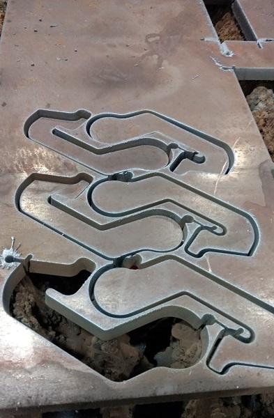
Strategically placed “bubbles” in the web enable edge starting in multiple places in the nest, avoiding the need for chain cutting or multiple pieces. Photo provided
The process of importing or drawing files, be it a PDF or from 3D CAD, and then cleaning and exporting them to machines involves a host of considerations, and it’s ripe territory for software. According to Jencks, this has been PEP Technology’s primary focus.
For most job shops, the order cycle starts with the estimate itself. “So many job shops quote based on spreadsheets about 80 percent of the time,” Jencks said, adding that estimates for new work might be based on assumptions that don’t reflect reality if and when the job runs.
Using a spreadsheet does save time, and quote turnaround can make the difference between winning and losing a job. According to Jencks, though, PEP can automate the file conversion and programming of the majority of parts, including those sent in as a PDF.
According to Jencks, within a few minutes, the software can produce a part drawing that can be nested and quoted. It has logic that tells it to find and categorize lines, texts, and title blocks. After categorizing the CAD data, the logic finds the flat pattern and develops a continuous path.
“And if the drawing has dimensions, the software compares the dimension to the part and scales everything in the file automatically,” Jencks said. For instance, the software scans the document for dimensions and scales the part to those dimensions. After scaling the part, the logic compares each internal cutout and external geometry to the dimensions.
“The software can convert about 80 percent of vector PDF files,” Jencks said, adding that converting PDFs of old drawings that were faxed (creating raster PDFs) has a success rate of around 20 percent.
When creating a nest layout, the software looks for areas ripe for material savings while also considering other attributes, including lead-in placement; the cut sequence; and material utilization, including the potential for common-line cutting. It weighs each factor against another variable common to any thermal cutting process, from oxyfuel to laser: heat dissipation.
Change the location of the lead-in or the cutting sequence, and excess heat rears its ugly head to cause a bad edge that requires secondary deburring, or just outright scrap. To mitigate heat effects, programmers sequence the cutting head to rapid frequently. They place teardrop “loops” to avoid excess heat buildup around sharp corners. And when flame cutting thick plate, they place locking lead-ins to prevent pieces from shifting due to thermal expansion.
“We don’t rely on that,” Jencks said, referring to a photo of a cut nest in 3-in.-thick plate, with cut parts having only 3/8-in. separation. At first glance the plate looks to be chain-cut, with kerfs connecting one profile to the next—but they aren’t chain-cut at all. If they were chain-cut, the nest layout would have lead-in-location constraints that would limit how each piece could be oriented in the nest and, in so doing, reduce material yield. They wouldn’t have small round cutouts placed throughout the web either—and those small cutouts, what PEP calls “bubble technology,” are key.
The torch performs an initial pierce and then cuts around the part, adding a bubble in a strategic location on the profile before continuing on to cut the rest of the first part. When the torch completes the first part, it moves to the previously cut bubble to edge-start and cut the next piece.
The location of the bubble, along with numerous other variables, “pushes the heat” toward areas that will have the least effect on the process and, hence, allow for those very thin web sections. Jencks added that not every thick plate nest requires those bubbles for thin webs and high material yield, but it’s there in the software’s toolbox if needed.
Predicting the behavior of heat (among other things) is also key for stable common-line cutting, as is typical slat conditions and orientation. Besides the obvious material savings, if stable and reliable, common-line cutting reduces the distance a cutting head needs to travel to complete a nest—with many kerfs creating edges for two parts. For this reason, the software typically common-cuts when it can do so without sacrificing material yield.
Of course, all that savings would be for naught if the cutting system crashed into a bowed part or poor edges required secondary deburring. It also would be for naught if it took forever to output such a nest in the first place. All the variables of programming—file imports; unfolding; sequencing; identifying and converting shapes like tangent arcs; material type and thickness; grain restraints for forming; strategic tabbing (or the avoidance thereof); the effects of heat—encompass a host of factors that need to be considered quickly and all at once. According to Jencks, this is where the potential of software and artificial intelligence shines.


The Fabricator is North America's leading magazine for the metal forming and fabricating industry. The magazine delivers the news, technical articles, and case histories that enable fabricators to do their jobs more efficiently. The Fabricator has served the industry since 1970.
start your free subscription
Easily access valuable industry resources now with full access to the digital edition of The Fabricator.

Easily access valuable industry resources now with full access to the digital edition of The Welder.

Easily access valuable industry resources now with full access to the digital edition of The Tube and Pipe Journal.

Easily access valuable industry resources now with full access to the digital edition of The Fabricator en Español.
In this episode of The Fabricator Podcast, Caleb Chamberlain, co-founder and CEO of OSH Cut, discusses his company’s...


