
Blaine Gibson (right) and Nick Connite (left) in Madagascar with two new pieces possibly from MH370.
In a newly released report, private investigator Blaine Gibson reveals details surrounding two new pieces that could be from MH370. The pieces were discovered by residents of Madagascar in September 2016, and delivered to Malagasy authorities on August 16, 2017.
Blaine writes that “for the protection of those involved, we decided not to make this report public until the debris was safely delivered to Malaysia.” That transfer was supposed to occur imminently. However, with the assassination of Hon Consul Zahid Raza, who served as a diplomat for Malaysia in Madagascar, the transfer has been delayed, and Blaine has decided to now release his report.
In the report, Blaine explains that “under the agreement between the two countries, debris is supposed to be collected by Hon. Zahid Raza, the Honorary Malaysian Consul in Madagascar, and delivered by private courier to Malaysia. On August 24 the Hon. Zahid Raza was assassinated in Antananarivo. The debris is still safely in the hands of the Madagascar Authorities. However new arrangements must be made for the collection and delivery of debris.”
Although not mentioned in the report, Blaine told me that during a trip to Madagascar, death threats were made to him and others for continuing to collect debris related to MH370. Blaine told me about these threats when I met with him on August 3, which was three weeks before Mr Raza was assassinated. The link between custody of the debris and the slain diplomat was first discussed in a previous post.
Blaine attributes the new discoveries to be the “result of the 370 families’ debris search and awareness efforts and travel to Madagascar.”
Twenty-seven photographs of the two pieces are available for download.
Of the two parts, the larger one was found on Maroantsetra Beach on Antongil Bay in September 2016. Blaine estimates the dimensions to be about 27 inches long, 12 inches wide, and 2 3/4 inches thick, and composed of a composite honeycomb structure. However, there is a 3 1/2-inch strip attached with fasteners that have not yet been identified as aviation related.

The two new pieces. The smaller piece (left) is more likely from an aircraft than the larger piece (right).
The smaller part was found on Antsiraka Beach around September 2016. Blaine estimates the dimensions to be about 12 inches long, 12 inches wide, and 3/8 inches thick, and composed of a composite honeycomb structure. This piece appears to have a higher possibility of being aviation related.
The pieces remain in the custody of Malagasy officials until new arrangements are made to transfer the pieces to Malaysia.
Blaine also has released new maps that show where it is in Madagascar that MH370 debris is predicted to wash ashore. The maps were created using computer models developed by Dr Charitha Pattiaratchi of the University of Western Australia. Blaine acknowledges that Dr Pattiaratchi and CSIRO’s Dr David Griffin have helped guide search efforts.
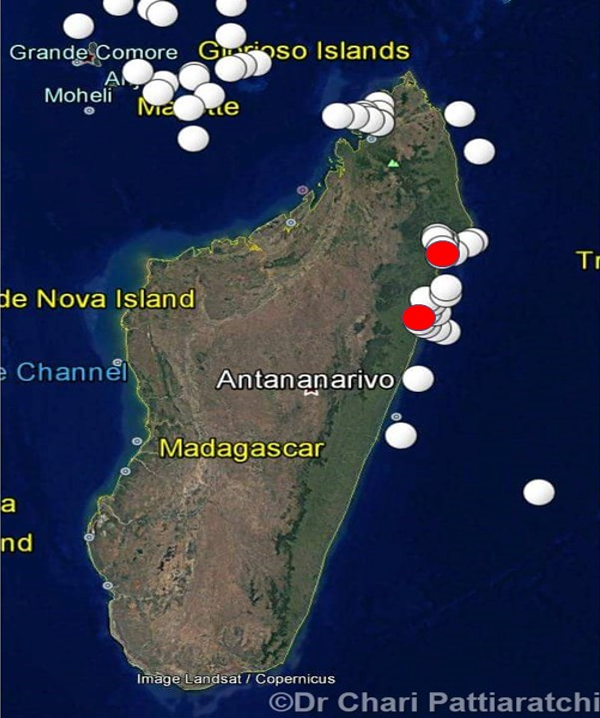
Location of MH370 debris as predicted by computer models (white) and where two new pieces were found (red).
The new report, debris photographs, and maps are available for download as a collection of files.
Update on Aug 29, 2017. The fasteners on the larger of the two pieces have been identified to be aviation related. Thank you to Annette Mansfield and Mike Exner for that information.
Final descent acceleration, from previous.
@Dr B, Gysbreght, Niels. Imagine you are in a glider in a level glide, slowing due to drag, when at fifty knots you push the nose down very quickly to vertical. Whereas previously your rate of descent was nil, now it is 50 knots and accelerating by the difference between the glider weight and drag. That is the principle. The change ROD will be set by the vector direction change plus subsequent acceleration. Certainly drag due to the aircraft form (shape and skin friction) will increase with speed but that will be offset by reduction in induced (ie lift caused) drag and for small speed changes the net effect I believe will be small.
The example follows that principle, just a nose down to a lesser degree.The vector will change in the same way and descent rate will increase, the acceleration being set not by the vertical 1g less drag but by the sine of the angle of descent, now less than 1, less drag. As to drag change, note that in the example the speed increase of 4500 fpm over 8 secs is small compared to the 40,000 starting speed and that being offset by reduced lift. In the example I estimated drag using a typical glide angle of descent increased a little to be conservative, not that this is the issue here.
If needs be I will draw up a vector diagram tomorrow and put into that what I say above, plus join others in having a look at your outcome Dr B. It is getting late here. Niels, there will be some transient forces, principally gravity resulting in the nose down vector direction change whether sudden or gradual but like a car turning a corner I do not think they will affect the main outcome. Gysbreght thanks for you input. Best expand on any continuing doubt.
@David @Mick Gilbert
I think there’s no real good comparison to the MH370 debris found so far.
Mostly ‘negative’ comparisons against high speed impacts. Which show quite different damage patterns and indeed (@David) fewer parts remaining afloat.
The ‘Hudson-ditch’ shows IMO similar ‘positive’ damage but this is also not well documented.
Then maybe AF447 shows ‘the best of both worlds’. Not what you would call a ‘ditch’ but also not a ‘high speed dive nose-first impact’.
A ‘nose-up, tail first, wings- level’ impact it has been in this case with almost no lateral speed.
Take a look at the recovered floating parts of AF447 compared with the parts found from MH370 so far and especially their positions.
Not quite the same ofcourse but remarkably similar IMO;
http://avherald.com/h?article=41a81ef1/0049
BTW I think the ‘final-BFO’s’ discussion is getting very interesting.
The timing of the 8 seconds ‘snap-shot’ and what could have caused this high accelaration in that short amount of time so soon (within 2 minutes) after the second engine flame-out can be crucial IMO.
Could it only have been a deliberate, controlled dive starting soon after second engine flame-out?
PS re the above, in case this helps, lift is perpendicular to the airflow direction well out in front. Drag is in line with airflow but in the opposite direction, so perpendicular to lift. In this case forward thrust is just that due to gravity, being the weight times sine angle of descent so acting in the opposite direction to drag, the difference causing acceleration (as per Newton equalling acceleration times mass). So in a glide with no acceleration the vector sum of lift plus drag is equal and opposite to weight.
@David: You ignore Newton’s second law which says that a moving object of mass continues at constant speed and direction unless a force is acting on it. You are considering only the forces and acceleration in the direction of movement. Changing the direction of movement(even at constant speed) requires a force and acceleration perpendicular to the direction of movement.
In the newtonion world your glider cannot change instantaneously from horizontal to vertical motion.
@David,
I think you are trying to re-invent Perpetuum Mobile.
If the last two BFOs were correct, the plane would have gained roughly 10,000 fpm (=51 m/s) of the downward velocity component during 8 seconds time interval. The average (over these 8 seconds) vertical component of the acceleration vector required for this would be 6.38 m/s^2 = 0.65g. Nose up or down, or the whole plane upside down – does not matter.
A very mysterious coincidence is that the 8-seconds interval of relatively high downward acceleration precisely overlapped with the 8 seconds of 00:19 logon timing. Even if you assume this acceleration began 4 seconds earlier starting from zero RoD, this would not solve such a mysterious overlap.
The second mysterious coincidence is that the second pair of (BTO, BFO) in 18:25 logon sequence was also corrupted.
@Oleksandr
“The second mysterious coincidence is that the second pair of (BTO, BFO) in 18:25 logon sequence was also corrupted.”
I agree.
@Gysbreght
Just thinking along on your comment;
‘In the newtonion world your glider cannot change instantaneously from horizontal to vertical motion.’
Then; ‘ Changing the direction of movement(even at constant speed) requires a force and acceleration perpendicular to the direction of movement.
I agree ofcourse. But then do you suggest a perpendicular force had to be applied deliberately to match the 8 seconds snapshot ROD?
Maybe elevator(s) down and (remaining) spoilers up, maybe even landing gear down (under remaining APU and RAT after) to descent very fast after second engine flame-out?
@VictorI
The nuts and bolts used in piece ‘7’ picture 20 and 21 sure look like aviation bolts and nuts. Also the inscriptions on top of the bolt.
Maybe @ALSM or someone alse can clearify for certainty.
@Victor
It is beyond belief that the debris is taking so long to make it to the appropriate MY authorities. Implication to me is just about zero curiosity among officials that an unknown mechanical failure could explain the accident.
@David @DrB @all
The other implication, since BFO is insensitive to Track at 32-36S (due to greater distance to the satellite) is the holy grail assumption of straight level flight for the whole flight is not a “given”. Intentional pilot adjustments, let’s say to straighten the flight trajectory after hitting 70-knot winds at 22S, or even a 90 deg turn to the East, would be hard to see after about Arc5.
I don’t like to state the obvious, but in light of the death threats against a MH370 debris searcher (Gibson), the assassination of the person tasked to transfer said debris (Raza) is highly suspicious.
Re: BFO values at 18:25 and 00:19
I often see comments like this: “The second mysterious coincidence is that the second pair of (BTO, BFO) in 18:25 logon sequence was also corrupted.”
The problem with such logic is that there is an unfounded a priori assumption that the values are “corrupt”. As soon as you accept the far more likely assumption that all the values are “accurate”, not “corrupt”, then you can start to understand what actually happened to cause these 4 particular values.
Bobby and I have provided a perfectly reasonable explanation for the 18:25 values. I based my analysis on decades of experience designing and testing satellite communications gear that employed TCXOs and OCXOs. I’ve spent many hours testing reference oscillators in an environmental chamber. Bobby took it a step further with his excellent curve fits. There is no doubt in my mind that we are looking at warm up drift (with an overshoot component) in the AES OCXO at 18:25. Indeed, if we did not see such a warm up pattern, it would be indicative of no extended power loss.
Likewise, if you simply assume the values at 00:19 were accurately recorded, then the ONLY explanation is a rapid and accelerating descent. You can not explain them due to changes in horizontal direction or speed, which after compensation, produce much smaller BFO value changes. Also, there is no coincidence in the timing. 2-3 minutes after FE, we should expect exactly that kind of descent starting (if there was no pilot). It all fits without any assumed corruption.
The starting assumption that these BFO values must be “corrupt” seems to arise only to fit various alternative starting assumptions about what happened in the cockpit. OTOH, if you assume these 4 values are like the other 1000 or so, and are simply 4 more values in a “good data set”, it is not that hard to understand what caused them.
TBill:
Re: “…since BFO is insensitive to Track at 32-36S (due to greater distance to the satellite) ”
The fact that the BFO values are relatively insensitive to track (and speed) has nothing to do with distance from the satellite. It is insensitive because ~98% of the aircraft horizontal Doppler is compensated in the AES, while none of the vertical Doppler is compensated.
@ALSM
Thank you. Does that behavior change over the flight path, or it is constant? My perception (from using CCYap’s *.xls to do hand calcs) is when the aircraft is between Arc2 and Arc3 passing the closest approach to the satellite, the BFO tells us more.
@CORRECTION
sorry I believe it is FFYap
@ALSM
“Bobby and I have provided a perfectly reasonable explanation for the 18:25 values. I based my analysis on decades of experience designing and testing satellite communications gear that employed TCXOs and OCXOs. I’ve spent many hours testing reference oscillators in an environmental chamber. Bobby took it a step further with his excellent curve fits. There is no doubt in my mind that we are looking at warm up drift (with an overshoot component) in the AES OCXO at 18:25. Indeed, if we did not see such a warm up pattern, it would be indicative of no extended power loss.”
No one is saying that your and DrB’s explanation for the 18:25 values is unreasonable or even implausible.
What I am saying is that the Holland paper written with review by the actual manufacturer of the equipment did not come to a similar conclusion. You are asking us to accept your explanation in lieu of the manufacturer’s explanation (the word “overshoot” does not appear once in Holland’s paper). In fact, as I am sure you recall, Holland characterized the 142Hz BFO value at 18:25:27 as an outlier and the subsequent BFO values as “settling” values.
I do have enormous respect for your (and DrB’s) experience and analytical skill. I am simply saying that for me the explanation for 18:25 BFO’s are not cast in concrete, and that the equipment manufacturer knows at least as much as you do about how the equipment behaves. I also cannot postulate any reason why the PIC would remove power from the AES by disconnecting an aircraft generator sometime between 17:05 and 18:xx.
@DrB:
I hope, you had a good time watching the solar eclipse. Sounds like.
Just wanted to thank you for your valued analysis.
I love and have a very deep respect for the ocean,
… and equally deep respect for researchers with a lifetime of accumulated scientific knowledge (in all fields, but particularly oceanographic), like you.
Didn’t understand your last line, though …
how can the swell be concurrently perpendicular and parallel to a NE-SW line ?
@Olexandr, if it was you who wrote that paper illustrating BFO-as-if-aircraft-velocity-info-missing, would you mind re-posting the link?
@DennisW
On your remark; ‘I also cannot postulate any reason why the PIC would remove power from the AES by disconnecting an aircraft generator sometime between 17:05 and 18:xx.’
By isolating the left IDG on the overhead panel just above him he could accomplish going dark completely in a matter of seconds; SATCOM, ACARS, IFE, transponders, main cabin lights would be disabled in one go pushing a few buttons.
If intended so this would have been the most efficient way to do it.
@ALSM: “Also, there is no coincidence in the timing. 2-3 minutes after FE, we should expect exactly that kind of descent starting (if there was no pilot).”
It is a strange coincidence because no one has been able to produce an unpiloted end-of-flight simulation that produces such high values of vertical speed and acceleration 2 minutes after FE. Therefore it is not the kind of descent that we should expect.
Dennis:
Re: “…the Holland paper written with review by the actual manufacturer of the equipment did not come to a similar conclusion.”
It would be more accurate to say that Holland and the engineers at Honeywell/Thales *today* came to NO conclusion. Apparently, they never thought about this explanation until I suggested it back in Feb. People that worked there 20-25 years ago might have better knowledge. And, unfortunately, the manufacturer of the OCXO is no longer in existence. That said, there is no reason why an experiment could be run today to verify the hypothesis. My understanding is that such an experiment had not been conducted as of Holland’s paper. I am still hoping to persuade Holland et.al. that is is important to run the experiments.
Back in February, shortly after Holland’s paper, I corresponded with him via ATSB relay. I explained to him the warm-up hypothesis, and he was apparently interested in the idea. In fact, we had a conference call planned to discuss this very issue. Unfortunately, on the day of the scheduled call, it was cancelled by DSTG (not ATSB) with no explanation. We were disappointed, but understood the sensitivity. Still hoping to have that discussion soon.
Frankly, I’m not surprised this explanation was not spotted earlier. If you are not an OCXO expert, no matter how much other detail you know about the MCS-6000, you might not ever think to dive into that rabbit hole. It took me a couple of years to see the pattern.
Can I ask you all a question ?
What do you think would have the bigger impact towards a worldwide effort to continuously track all passenger aircraft at all times:
if MH370 is found or if it remains missing ?
And why ?
A few comments/questions: 1) The Pattiaratchi map that BG refers to reminds me that the Comoros may have been as much a hotspot for debris as northern Madagascar. Presumably BG chose to go to Madagascar in part as more tourist friendly and safe. Ironic given the Raza assassination.
2) Note that the ‘new’ items were found in 2016. In theory, natant debris in the gyre would continue to circulate and come ashore after additional orbits. I’m guessing that most or all debris has lost buoyancy and sunk, or broken up into unrecognizable fragments, and that the decay curve has effectively reached zero.
3) Is it clear what BG has handed over to Madagascan authorities and is still in their hands? My recollection was that most or all of the previous Malagasy material [Riake Beach, etc] was already included in the 2017 reports.
lkr says: “Presumably BG chose to go to Madagascar in part as more tourist friendly and safe.”
From my experience (having lived in the area) the Comoros are regarded as safer (than Mada).
@TBill said, “My perception (from using CCYap’s *.xls to do hand calcs) is when the aircraft is between Arc2 and Arc3 passing the closest approach to the satellite, the BFO tells us more.”
Your impression is correct, but not because it is the point of minimum range to the satellite. Rather, at that time, the satellite was at its peak declination (latitude). The Doppler compensation algorithm in the SATCOM used a model with a geostationary satellite. The ability to compensate for the horizontal component of aircraft velocity varies with declination of the satellite. The BFO will be more sensitive to horizontal velocity if the compensation is incomplete. At around 19:36, the declination was about 1.64°. At 00:19, the declination was about 0.54°. Therefore, at 00:19, the Doppler compensation algorithm will more effectively cancel the uplink Doppler, and the BFO will be less sensitive to horizontal velocity.
IKR:
Re: “Is it clear what BG has handed over to Madagascan authorities…” Yes. It is well documented in Victor’s post. See dropbox links therein.
Re: “…is [it] still in their hands? Yes. I verified this with an official in Malaysia. The Madagascar Civil Aviation authorities have it.
Re: “My recollection was that most or all of the previous Malagasy material [Riake Beach, etc] was already included in the 2017 reports.” These are 2 new pieces of material. ATSB and Malaysia have had the photos for some time, but not the debris. Blaine explained the reasons for the long delay getting them handed over to Malaysia when he was here last week. It had a lot to do with the desire of the parties to establish a specific protocol for the transfer of this and any future debris. In addition, the death threats were a major concern for the safety of people involved. If it were not for the safety and protocol issues, Blaine could have hand carried them to Malaysia or ATSB last year, like some of the previous finds.
@Gysbreght said, “It is a strange coincidence because no one has been able to produce an unpiloted end-of-flight simulation that produces such high values of vertical speed and acceleration 2 minutes after FE.”
That’s not true. Mike Exner witnessed a simulation where the rudder trim was set to zero and both engines flamed out at about the same time. Within about 40 seconds, one engine began a restart spool up, and about a minute later, the aircraft was banked and in a steep descent from the asymmetric thrust. The attempted restart of the engine could also explain the repowering of the SATCOM and the log-on.
@Ge Rijn: “But then do you suggest a perpendicular force had to be applied deliberately to match the 8 seconds snapshot ROD?”
No, I’m not suggesting that a perpendicular force had to be applied deliberately to match the 8 seconds snapshot ROD. The ROD values 8 seconds apart could have been matched when the airplane was accelerating along a linear path about 45 degrees below the horizon.
@all
Last week a couple of us were talking about possible ships in the area during the MH370 crash. Mike Chillit is recently talking about that and showing some of the shipping activity.
https://pbs.twimg.com/media/DIVyZSAUIAAfS-m.jpg
@Paul Smithson,
https://www.dropbox.com/s/r551bp495n2juoc/TN-ABFO-Rev1.0.pdf?dl=0
@Ikr,
Re: “Note that the ‘new’ items were found in 2016. In theory, natant debris in the gyre would continue to circulate and come ashore after additional orbits. I’m guessing that most or all debris has lost buoyancy and sunk, or broken up into unrecognizable fragments, and that the decay curve has effectively reached zero.”
Both CSIRO’s and my drift models predict high concentration of debris along almost all the east coast of Madagascar. In my estimation 30-40 more fragments could be waiting there (btw, I am not sure why Pattiaratchis’ model does not show this – perhaps too short simulation time?). I am not sure what methodology is followed by Gibson, but I am sure he will be able to find a lot more debris if he gets some logistic support and volunteers, and searches further southward.
But another question is whether these debris are worth of the time and effort? They would not tell anything new.
@Victor,
Re: “Mike Exner witnessed a simulation where the rudder trim was set to zero and both engines flamed out at about the same time. Within about 40 seconds, one engine began a restart spool up, and about a minute later, the aircraft was banked and in a steep descent from the asymmetric thrust.”
Any data in digital format including RoD?
@ALSM,
“The problem with such logic is that there is an unfounded a priori assumption that the values are “corrupt”. As soon as you accept the far more likely assumption that all the values are “accurate”, not “corrupt”, then you can start to understand what actually happened to cause these 4 particular values.”
You mix apples and oranges. The term “corrupt” or “abnormal” relates to the fact that these BFO values can not be explained within the frame of the theory published by, for example, ATSB in 2014. There must be other terms, which alter BFO, such as the term responsible for your overshot. Nothing to with the “accuracy”.
I think your theory perfectly explains logon 00:19. But it goes against 6 curves presented by Holland and against his conclusions when you attempt to apply it to 18:25 logon, as explained early by Dennis. In addition, when you apply you theory to 18:25 logon and do not apply it to 00:19 logon, you implicitly assume a batch of coincidences, joint probability of which would be “astronomically low”.
Can you explain what was a reason for the abnormally large BTOs in both the instances? Why only these two instances?
@Peter Norton,
You said: “Didn’t understand your last line, though …
how can the swell be concurrently perpendicular and parallel to a NE-SW line ?”
What I meant was this: The crest/trough of a swell/wave will be perpendicular to its direction of motion. Thus, the crests/troughs, which generate the sunglint, will be perpendicular to a NE-SW line and will be moving parallel to a NE-SW line. What is seen in the Pleiades single frames is a NW-SE orientation, i.e., perpendicular to the NE-SW direction of motion.
@DennisW,
You said: ” I also cannot postulate any reason why the PIC would remove power from the AES by disconnecting an aircraft generator sometime between 17:05 and 18:xx.”
Neither can I, especially when you also consider the restoration of power at ~18:22. The power loss may not have been caused by an intentional act, but the power restoration almost certainly was.
@Peter Norton
RE: “What do you think would have the bigger impact towards a worldwide effort to continuously track all passenger aircraft at all times: if MH370 is found or if it remains missing ?”
ICAO has already amended Annex 6 to include standards and recommended practices (SARPS) relating to continuous aircraft tracking. That work began shortly after the disappearance of MH370 and was also a response to the disappearance of AF447, which took two years to find.
The Annex 6 amendments include SARPS for both normal aircraft tracking (NAT) and autonomous distress tracking (ADT). The NAT SARPS are applicable from November 2018, and require aircraft operators to track the position of their aircraft at 15 minute intervals throughout their area of operations. The ADT SARPS require aircraft to ‘autonomously transmit information from which a position can be determined at least once every minute when in a distress condition’. They are applicable to all new aircraft with a take-off weight greater than 27,000 kg from January 2021.
https://www.icao.int/safety/globaltracking/Pages/GADSS-Update.aspx
http://airlines.iata.org/analysis/tracking-aircraft-everywhere-is-almost-within-reach
@ALSM,
You said: “The starting assumption that these BFO values must be “corrupt” seems to arise only to fit various alternative starting assumptions about what happened in the cockpit. OTOH, if you assume these 4 values are like the other 1000 or so, and are simply 4 more values in a “good data set”, it is not that hard to understand what caused them.”
Well said.
@Gysbreght
RE: “It is a strange coincidence because no one has been able to produce an unpiloted end-of-flight simulation that produces such high values of vertical speed and acceleration 2 minutes after FE.”
We don’t know the exact starting conditions of Boeing’s simulations, but the ATSB report MH370 – Search and debris examination update dated 2 November 2016 states the following:
“The results have all been aligned to the point two minutes after the loss of power from the engines. This is the theorised time at which the 7th arc transmissions would have been sent…
…Some of the simulated scenarios recorded descent rates that equalled or exceeded values derived from the final SATCOM transmission. Similarly, the increase in descent rates across an 8 second period (as per the two final BFO values) equalled or exceeded those derived from the SATCOM transmissions. Some simulated scenarios also recorded descent rates that were outside the aircraft’s certified flight envelope.”
Is the timing of the high descent rates suggested by the SATCOM transmissions really so ‘mysterious’ or ‘coincidental’ when it can be explained by the ATSB’s end-of-flight scenario?
@Gysbreght,
You said: “No, I’m not suggesting that a perpendicular force had to be applied deliberately to match the 8 seconds snapshot ROD. The ROD values 8 seconds apart could have been matched when the airplane was accelerating along a linear path about 45 degrees below the horizon.”
If the aircraft was flying at a constant 45 degrees below the horizontal, its speed at 00:19:29 would have to be about 61 kts to match the BFO then. 8 seconds later the speed would have to be about 207 knots. That implies an acceleration along the direction of the flight path of ~0.96G’s (which requires a combination of gravity and thrust). Of course, the aircraft could not fly at such low speeds, so such a scenario does not seem possible.
@David,
If the aircraft were nose-down at 13 degrees at 00:19:29 its speed would need to be 193 kts, and 8 seconds later its speed would need to be 323 kts, in order to match the BFOs. This implies an average acceleration parallel to the aircraft longitudinal axis of 0.85 G’s, most of which would have to come from thrust with some contribution from gravity.
There are some BFO solutions involving constant airspeed (and therefore having zero average longitudinal acceleration). For instance, at 300 kts you need -8.3/-29.2 degrees. At 350 knots, you need -7.1/-24.7 degrees. At 400 kts you need -6.25/-21.5 degrees. In all these cases, you need a force/moment (drag) to change the attitude (nominally pitch) of the aircraft. The drag associated with lowering the nose would also bleed off airspeed, and gravity would then tend to increase the airspeed when nose down. For these simple calculations, I assumed the speed was the same at the two points in time (8 seconds apart). For reasonably high and flyable speeds, the angles must be smaller than those proposed by David. Near 400 kts the pitch rate is less than 2 degrees/s. Maybe Andrew can comment on the feasibility of such a pitch rate. Would it overstress the aircraft? Would control surfaces flutter?
@Irthe Turner
In regards to the PIC being unable to cope with the cold-blooded reality/aftermath of his actions and impulsively taking his own life post-FMT, I would put the chances of this scenario at close to zero, beyond miniscule. He surely was well rehearsed and well-prepared to deal with this eventuality that he was solely responsible for. He knew he would be murdering hundreds and he understood full well the implications. He just didn’t care, so great was his need for revenge and the final word.
I would also put the chances that the PIC PLANNED (pre-meditated) to take his own life post-FMT and before achieving terminus at close to zero. This is the final and most significant task of this man’s life. You don’t go to sleep until you are SURE of success and outcome.
Why people continue to believe that this could be a deliberate ghost flight is troubling. The EOF flight data and scenarios MUST Be married with active control inputs until near-impact. Whether steep dive or dive, glide and ditch. People are kidding themselves and doing a great disservice to others by stubbornly clinging to a ghost flight EOF. It’s lamentable.
Furthermore, I would put the chances that the PIC failed in his mission either by accident or unplanned for intervention (like the ridiculous idea of the FO pulling stuff in the EE bay) at near zero. I say this given it looks to me like he accomplished exactly what he set out to do.
Oleksandr:
Re: “I think your theory perfectly explains logon 00:19.” Thanks.
“But it goes against 6 curves presented by Holland and against his conclusions when you attempt to apply it to 18:25 logon…” No, it is 100% consistent with what Holland published. Holland simply did not know what caused the first 2 BFO values at 18:25. His time scale did not take into account the variable time it takes before a reboot can occur, depending of the BITE logic and preceding power off time. All of his curves can be explained, as Bobby did so well.
“In addition, when you apply you theory to 18:25 logon and do not apply it to 00:19 logon, you implicitly assume a batch of coincidences, joint probability of which would be “astronomically low”.” We assume no coincidences. The same theory applies to all logons, including those for MH371. But the results vary depending on the preceding power off time, as Bobby and I have explained many times. It all fits.
“Can you explain what was a reason for the abnormally large BTOs in both the instances? Why only these two instances?” I assume you meant BFOs, not BTOs. If so, they are completely explained buy the warmup overshoot hypothesis, again, as explained many times before.
@DrB
I think the correct angle for Gysbreght’s “linear path” would be around 56 degrees nose down (arcsin(sqrt(0.68)), assuming no thrust and no friction.
Concerning the pitch rate, perhaps this is an interesting read:
https://en.m.wikipedia.org/wiki/Reduced-gravity_aircraft
I will put my ditch preference aside for a minute.
Let’s assume thet the dive theory is correct.
In that case, it has to be (somewhere) on, or very near, the arc. The question then becomes, where (latiitude wise) on the arc.
The southern limit of the area so far searched, without result, was bounded by the maximum possible fuel range from the FMT north of Ache. I will call this the “NORTHERN FMT”.
I, (as you are all probably well aware) have long disputed the sense of a “deliberate act / plan pilot” flying up the Malacca Strait to begin with. I still think the aircraft continued WSW from Penang directly across Sumatra, and that the real FMT was west of Sibolga. Let’s call that the “SOUTHERN FMT”.
Now, the simple fact is, that from Penang at 17:52, there is a segment of the 18:25 arc that is reachable. Indeed, even Penang is not a slam-dunk. Let’s go back to Igari at 17:20. From 17:20 to 18:25 is 65 minutes, and the possible “segment” of the 18:25 arc that could have been reached is a little longer than that from Penang, but either way, the 18:25 arc does have a northern limit, and a southern limit. I think I recall that even ALSM put up a graphic at some point not long ago, that even begrudgingly conceeded that point, at least.
The southern limit has not been considered by anyone else (so far as I know), seemingly, simply because everyone has accepted that the 18:22 final radar hit is real.
There is so much about the porcity of radar data, and the provinence of what radar data that has been presented, that a blind acceptance of the 18:22 hit simply leaves me speechless.
If we accept that Fugro did a good job, and that they did not “miss it”, then sticking with the “NORTHERN FMT”, in the face of a confident “not found here” on the 7th arc, is illogical.
If you accept the possibility of a “SOUTHERN FMT”, then the search should have extended another 300 nautical miles further south west along the arc.
My question is, why does everyone still stick with the supposed 18:22 hit, really ?
The Malaysians have been less than helpful from day one, they have been less than interested in collecting debris, and the latest threats to BG and the assaination all speak towards them NOT wanting the aircraft found. Sticking to the NORTHERN FMT, has produced no result, and seemingly assures that it will not be found.
I therefore respectfully submit to ALL, that, if David Grifin’s 35S rogue current turns out to be wrong (IT MUST BE SEARCHED – I AGREE) then there are only two posibilities left.
1. It must be way further north – as Mike Chillit has long contended, or:-
2. It must be a little FURTHER SOUTH-WEST ALONG THE ARC, (regardless of the drift studies indicating otherwise).
In that case, why not go back to square one as it were, “set aside” the 18:22 constraint, indeed, “set aside” the whole Malacca Strait story, and “SERIOUSLY” consider the maximum possible southern limit of the 18:25 arc reachable from Igari, and do all the sums again ?
@Olex: I do remember your models, though I no longer have hard copies. If I remember correctly, you tested starting points over a very wide gamut, from 22S or so all the way to 40S. I thought they were useful, though mostly arguing for absence, eg in WA, Sumatra, Sri Lanka. For origins in the 30S to 35 range, I recall general similarity again to Pattiaratchi’s later pubs, though I think you DIDN’T show arrivals in the Comoros.. [I, and most here, take absence in WA seriously, but not so much anywhere else.] Also, as I recall, some of your starting points at least made arrival in South Africa feasible.
@Pter Norton: “lkr says: “Presumably BG chose to go to Madagascar in part as more tourist friendly and safe.”
From my experience (having lived in the area) the Comoros are regarded as safer (than Mada”
OK, I deserved that for a somewhat snarky remark. Clearly BG could not cover the entirety of the western shore in person, so he went to a well-developed series of tourist beaches where he could cover a lot of ground [with ATV, yes?], as well as recruit local helpers. From the same map, a BG wannabe certainly could have headed for Comoros. Just another lost opportunity.
@DrB
RE: “Maybe Andrew can comment on the feasibility of such a pitch rate. Would it overstress the aircraft? Would control surfaces flutter?”
The B777’s load factor limits are +2.5g to -1.0g (flaps up), the same other transport category aircraft. However, the ultimate load factor the manufacturer is required to demonstrate during certification is 1.5 times the limit load factor, ie +3.75g to -1.5g. The B777 wing was tested to destruction during certification – the wing broke at 1.54 times the limit load factor, equivalent to +3.85g. The wing wasn’t tested in the negative sense, but Boeing’s structural analysis must have shown that it was capable of withstanding at least -1.5g.
I doubt that flutter would be a problem at the speeds mentioned in the discussion.
A further point on the subject of “radar”.
I read somewhere that the ATSB’s maximum NW Point was apparently deduced from a “non specified”, and “non identified” Singapore radar’s “not-seen”, and was calculated as 8.595317°N 92.585750°E. I don’t remember where I saw that, but I saved that position and put a pin for it in my Google Earth.
I can only interpret that point, as a means of ensuringing that a southern limit was set for the search. The question is, why ?
That, viewed in the light of recent eents, suggests that:
(a) The tripartite statement of conditions REQUIRED for THEM to resume the search, was deliberately, and very cleverly drafted, in such a manner, as to ensure the non specicivity of both what will (for them) constitue “new” and “precise”. was to ensure, that they could never be nailed down on either “a new” or “a precise”, so that they could never be forced to resume the search.
(b) So, it is obvious that the Tripartite Governments clearly have no intention of ever resuming the search, and thus, have no commitment to actually finding MH-370, regardless of the “crocodile tears”.
(c) Therefore, we must now support the private search option(s).
@DrB,all. Here is a vector diagram illustrating how pitch down can satisfy the BFOs essentially by pitching down velocity vector. If incomprehensible please say so and I will break it down into a step by step. The diagram is basic in character because the aerodynamics and mechanics are very basic. My apologies though for the ‘quick sketch’ presentation.
Please note that without gravity the change of velocity vector direction towards the earth could be realised by an aerodynamic force in that direction, ie a temporary negative lift. With gravity one can realise such a force just by reducing lift, that is by pushing forward on the controls or by banking and reducing lift that way. The principle there is demonstrated in green in the diagram.
There is no ‘need’ for any downwards speed acceleration at all. If gravity were cut off during a nose down the aircraft could still realise the both BFOs simply by going a little more nose down than before to meet the second BFO descent rate. In this case the ROD of 20,000 fpm could be attained by a nose down from the 13˚ descent, 9,000 fpm to 30˚, in place of the example’s 27.5˚.
Please check this yourself, noting the ROD triangle in the diagram. TAS of 40,000 fpm multiplied by sine of the descent angle, now 30˚ yields 20,000 fpm. So apart from turning the aircraft speed vector downwards, there need be no gravity or downwards acceleration at all.
I ask for any disagreement to be explanatory as distinct from just an assertion.
Dr B. I think that the zero gravity 13˚ to 30˚ above is simple and as yet I can see no grounds to argue against that hypothetical acceleration free outcome; that it will meet the BFO descent rates just by progressively pointing the nose down, using pitch or bank to reduce vertical lift. Adding acceleration due to gravity is a refinement, reducing the nose down otherwise required.
Does the diagram and above make a difference to what you have done?
https://www.dropbox.com/s/vjmipipjglxavh7/Rate%20of%20descent%2C%20nose%20down.pdf?dl=0
@Ge Rijn. AF447 wreckage. I see what you mean. “Recovered control surfaces include some aileron parts and some elevator parts, all of which show damages caused by a bottom-upward load.”
Unclear what of that recovered was afloat but the life jackets raise a, “..Dog That Didn’t Bark” question as to for how long life jackets and life rafts float. There might have been some seat cushions washed onto Reunion and burnt as I remember it. Should we have expected to see life jackets and rafts if the MH370 cabin was badly broken?
You ask, “Could it only have been a deliberate, controlled dive starting soon after second engine flame-out?”
For my part it could not since surely he would have exceeded the 0:19:29 BFO descent starting that early.
@Gysbreght. “You ignore Newton’s second law…” Not so much ignored as not central at the time, but you will see from my green diagram he now has a rightful spot via centripetal force due to gravity.
@Oleksandr. “A very mysterious coincidence is that the 8-seconds interval of relatively high downward acceleration precisely overlapped with the 8 seconds of 00:19 logon timing. Even if you assume this acceleration began 4 seconds earlier starting from zero RoD, this would not solve such a mysterious overlap.”
Yes we do not have data on when the descent started. As many have indicated it depends on copious uncertainties but I think Andrew has commented on the coincidence question. To me it is the default explanation because it is the most plausible offering. It would be really nice to know what the probability is of exactly meeting those times but then again it is like asking what the probability of a car accident at, exactly at time X and exactly at place X, both randomly chosen.
One of the above uncertainties is whether the simulator faithfully replicates the aircraft in extremis, which the ATSB has acknowledged.
@David,
I understand exactly what you did. Your diagram looks like mine.
You said: “There is no ‘need’ for any downwards speed acceleration at all.”
I’m not sure I understand exactly what you meant by this. A downward acceleration is always required for the aircraft to descend. This downward acceleration is the vector sum of gravity and the rate of change of lift. If a not-very-high downward acceleration is needed (up to -1 G), then of course all you have to do is reduce the lift and let gravity do the job. If you need more than -1G, then the lift must become negative so it can supplement gravity.
Yes, I agree that that the airspeed does not have to change. That’s why I said “There are some BFO solutions involving constant airspeed . . . .”
The two final BFOs are matched when the vertical speeds are about -43 kts and -147 kts, respectively. Any combination of airspeed and pitch angle giving those vertical speeds will match the BFOs. I gave several examples at constant speed and at varying speed. The varying speed at constant angle does not seem to work in practice for the reason I mentioned (too low speed).
You said: “Dr B. I think that the zero gravity 13˚ to 30˚ above is simple and as yet I can see no grounds to argue against that hypothetical acceleration free outcome;”
The grounds for arguing against it are two:
1. Using your 13/30 degrees, in order the match the measured BFOs the airspeeds need to be 193 kts and 293 kts. Those speeds, especially the first, don’t appear to me to be flyable at altitude.
2. The outcome is not acceleration free. An average longitudinal acceleration of 0.66G’s is needed to speed up in the 8 second interval.
@Niels,
You said: “I think the correct angle for Gysbreght’s “linear path” would be around 56 degrees nose down (arcsin(sqrt(0.68)), assuming no thrust and no friction.”
At 56 degrees pitch, the airspeed at 00:19:29 would need to be only 57 kts, increasing to 177 kts 8 seconds later. This is also not flyable.
@Andrew,
Thank you for providing the loading limits and test results. At normal airspeeds, it appears the aircraft could pitch/bank fairly steeply (enough to satisfy the BFOs) without immediately shedding control surfaces. That’s what I wanted to know.
> @all
> Last week a couple of us were talking about possible ships in the area
> during the MH370 crash. Mike Chillit is recently talking about that and
> showing some of the shipping activity.
> https://pbs.twimg.com/media/DIVyZSAUIAAfS-m.jpg
Can someone tell me what those cyan spots are ?
Fishing-related, given the nearby Korean/Japanese fishing fleet ?
Are they related to plankton/chlorophyll concentration in the water ?
http://www.buoyweather.com/infowide.jsp?id=42032
And what is the red spot on Australia’s West Coast ?
@Victor. Your response to Gysbreght. “The attempted restart of the engine could also explain the repowering of the SATCOM and the log-on.”
Interesting that. I think you had mentioned it earlier. I think relight of the right engine would be only after an attitude change shifted fuel so some covered the gravity/syphon inlet, which would have been uncovered at flame out. RR relight commences beneath idle I seem to remember and an engine takes a while to regain idle. Then the IDG has to come back on line and that for a minute 8 secs. Looks like an ask to me.
The left engine would have access to a similar syphon plus APU pump residual fuel. Even so for that to start and run for long enough without coughing seems doubtful. I wonder where the simulator reckoned that fuel was available from after nominal exhaustion since the residual APU fuel availability has been determined only recently. I would assume the syphoning would be very attitude dependent so the fuel-for-start attitude would have to be held. So any run as distinct from a relight would be chancy and doubtful IMO.
@Andrew: “Is the timing of the high descent rates suggested by the SATCOM transmissions really so ‘mysterious’ or ‘coincidental’ when it can be explained by the ATSB’s end-of-flight scenario?”
Yes, because the ATSB will not confirm that their 8 seconds periods were at the time of final SATCOM transmission. The trajectories shown in figure 6 of their report suggest that they were not.
You’ll remember that we’ve been through that at the time (november 2016). If you look at the trajectories shown in figure 6 of that report, you’ll see that at the point at which the 7th arc transmissions would have been sent the radius of all trajectories is of the order of 10 NM, corresponding to a bank angle of about 10 degrees at FL350, 200 kCAS.
After that point the radius in trajectories 7 through 10 (*) the radius rapidly reduces and each ends in what looks like a very tight spiral turn. Those are the trajectories that represent the simulations in “an electrical configuration where the loss of engine power from one engine resulted in the loss of autopilot (AP)”. They are also four of the five simulations that “recorded descent rates that equalled or exceeded values derived from the final SATCOM transmission.”
Regarding the sentence “Similarly, the increase in descent rates across an 8 second period (as per the two final BFO values) equalled or exceeded those derived from the SATCOM transmissions” I’ve asked the ATSB to confirm that the 8 second period was at the time of the final SATCOM transmission. It’s now five months later and I’m still waiting for their reply.
(*) I’ve numbered the trajectories from left to right at the top of the chart.
@Dr B. Thanks for that. You quoted me, “There is no ‘need’ for any downwards speed acceleration at all.” and added, “And I’m not sure I understand exactly what you meant by this.” I was hypothetically removing gravity as a cause for downwards speed acceleration just to indicate speed acceleration was unnecessary to meet the BFOs, though of course it is needed to swing the vector down as per my green diagram. My wording could have been clearer. I have not seen the realisation of the nose down of <2˚/sec as being an issue having a very high bank in mind in particular as a solution. In my diagram the tail upright was mostly for clarity and really to indicate it could be, not that it must. That is why mostly I generally use the term nose down rather than pitch down, except where the latter applies specifically.
Your 43 kts and 147kts ROD are close to the minimum ATSB BFOs whereas my equivalents of 89 and 197 kts aim midway between their maxima and minima, which makes quite a difference. Do you plug for the minimum end for a reason?
At my nominal 400 kts TAS the nose down needed to reach those minimum BFOs is a touch over 6˚ and 21.5˚. If I took account of the speed acceleration between the two, the 21.5˚ would be less.
On your first grounds for arguing against my hypothetical outcome was that it resulted in low airspeeds. Leaving aside this hypothetical for the moment, you should not work backwards from my 13˚ and 30˚ since those are derived, the basis being 400 knots, at which the above 6˚ and < 21.5˚ apply if the aim point is reduced to the ATSB minima.
Your second grounds for arguing against zero gravity, “The outcome is not acceleration free” applies not to my example but to the hypothetical which as above was merely to demonstrate how there could be a reasonable solution even without any speed acceleration at all. It served to illustrate how unsound was the 0.68 g vertical acceleration supposition. It was not intended to replace my example where as you know speed acceleration due to gravity was included and made matching of the BFO descents easier still.
I hope that you will continue to find reason to look into this. I have not yet been able to look into an earlier post of yours but will.
@ Dr B. Having taken a closer look now at your Aug 28, 5:51 am, I see that what you have found in your researches such as, “BFO increases by ~18Hz as true bearing changes from 180 degrees to 0 degrees” and, “So the BFO is very insensitive to horizontal speed and rather insensitive to the track. The vertical speed dominates”, are consistent with my principal reference and guide, the ATSB Search and debris examination update of last November, pages 1-6.
Even the different BFO descent rate criteria may not intrude much.
@DrB: “Of course, the aircraft could not fly at such low speeds, so such a scenario does not seem possible.”
I believe you are right, essentially. I didn’t look at it from that angle, and only sought to match the longitudinal acceleration. The number you quote would depend on the bearing, wouldn’t they?
Please ignore the second sentence in your quote.
@ Niels: “I think the correct angle for Gysbreght’s “linear path” would be around 56 degrees nose down (arcsin(sqrt(0.68)), assuming no thrust and no friction.”
Agreed, except that I calculate the vertical acceleration as 0.63 g (184 Hz = 9684 fpm change in 8 seconds). To that I would add 0.08 to account for the drag-to-weight ratio demonstrated in ALSM’s simulation).
@DrB + @Andrew:
thank you both for the information (swell & aircraft tracking)
@lkr:
RE: “OK, I deserved that.” I merely wanted to give you the information.
Oddly enough, the data I find on the net, contradicts my statement (which reflects the opinion of many people I talked to living in the area):
http://www.nationmaster.com/country-info/profiles/Comoros/Crime
http://www.nationmaster.com/country-info/profiles/Madagascar/Crime
@Victor
@David
@Victor said: “Mike Exner witnessed a simulation where the rudder trim was set to zero and both engines flamed out at about the same time. Within about 40 seconds, one engine began a restart spool up, and about a minute later, the aircraft was banked and in a steep descent from the asymmetric thrust.”
@David said: “Interesting that. I think you had mentioned it earlier. I think relight of the right engine would be only after an attitude change shifted fuel so some covered the gravity/syphon inlet, which would have been uncovered at flame out. RR relight commences beneath idle I seem to remember and an engine takes a while to regain idle. Then the IDG has to come back on line and that for a minute 8 secs.”
The RR Trent engine’s auto relight function supplies power to the igniter plugs as soon as the EEC detects a flame-out. That should occur well before the engine slows down below idle.
I believe the left engine is more likely to have restarted than the right. ELMS would have initiated the APU autostart sequence as soon as the second engine failed and electrical power to the transfer buses was lost. The APU dc fuel pump would have started and the APU isolation valve and APU fuel shutoff valve would have opened, allowing the APU dc fuel pump to supply fuel to both the APU and the left engine. The engine’s auto relight function should have already activated by that time, supplying power to the igniter plugs. With fuel and ignition available, the engine may have restarted at the same time as the APU if the engine’s RPM was still high enough to allow a windmill start.
@Andrew: I believe there are two ways that the high RoDs could have occurred: a nose-down pilot input, or the aircraft entered into a bank. If we put aside the pilot input for now, we have to look at what could have caused the bank when in secondary mode (in light of the dihedral stability of the B777, which would tend to keep the wings close to level). Possibilities include rudder out-of-trim, flaperon asymmetry under RAT power, and engine restarts. The engine restart is intriguing to me because it could explain the SATCOM reboot (as the engine spools up past idle and the associated IDG becomes operative) and the bank (due to the thrust asymmetry leading to yaw and inducing roll). Looking at the simulation that Mike witnessed, the engine restart induced a steep bank about a minute after the restart began. That’s also the timing for the SATCOM to request a log-on after power is restored. It explains the timing of the steep descent and the SATCOM log-on.
@Victor
Thanks – a sudden burst of asymmetric thrust with the TAC inoperative (as it would be with the flight control system in alternate mode) would certainly induce a high rate of yaw and roll. If the left engine was the last to fail, then the thrust lever would have been at the CLB thrust position before it failed, as the autothrottle attempted to maintain the aircraft’s speed. It would have remained in that position when the engine subsequently flamed out. If the engine subsequently restarted, it would have eventually accelerated back to its previous thrust setting, assuming there was enough residual fuel remaining for it to keep running.
Thinking along again.. when an APU restart was possible after second (right) engine flame-out then also a left engine restart was possible considering both were fed by the left wing main tank.
Maybe after an initially set-in left bank after second engine flame-out due to left flaperon upwards (bypass) position and residual (left)rudder trim, remaining left tank fuel became available to the left engine again also (as to the APU).
But then if this happened, would not have the left engine’s thrust pulled it out of a bank and let the plane fly wings level again?
@David said at 1:05 am: “I think relight of the right engine would be only after an attitude change shifted fuel …”
Let’s get this straight. Attitude defines the orientation of the airplane relative to the direction of gravity. An attitude change, by itself, does not shift the fuel. Each attitude change is associated with a change in longitudinal acceleration that is equal in magnitude and opposite in direction to the change of the longitudinal component of gravity. Pitch down and the airplane accelerates. Pitch up and the airplane decelerates. In both cases no effect on the level of fuel relative to the tank.
New piece from Geoff Thomas discussing recent events in Madagascar.
(Hopefully, he corrects some of the typos, e.g., “Mr Blaine”, “Mr Innello”).
@Ge Rijn
Any TAC inputs would have been removed as soon as the second engine failed and the flight control system reverted to secondary mode, so there was probably little (if any) rudder trim input. Further, I suspect any left rolling moment caused by the up-float of the left flaperon would be much less than the right rolling moment induced by asymmetric thrust from the left engine if it restarted.
@David,
Re: “Yes we do not have data on when the descent started. As many have indicated it depends on copious uncertainties but I think Andrew has commented on the coincidence question. To me it is the default explanation because it is the most plausible offering. It would be really nice to know what the probability is of exactly meeting those times but then again it is like asking what the probability of a car accident at, exactly at time X and exactly at place X, both randomly chosen. ”
Imagine we have descent of 5,000 fpm at 00:19:29 immediately followed by the average downward acceleration of 0.68g over the next 8 seconds for whatever reason. Unless it was a plugoid, I would risk to suggest that the beginning of the descent would be known rather accurately – 00:19:25.
Regarding probability. Boeing ran a dozen or a few dozens of simulations. Assume 1:10 simulations showed similar descent as derived from the BFO data. Now take the SDU startup: it may occur any time within 4 minutes after the power first applied, subject of meeting certain logical conditions. We don’t known how long the SDU was depowered. Assume it took 1 minute to restore power, and 1 minute for the SDU to start transmitting. Then the probability of the coincidence of the time intervals in question would be 8/60. Multiply it by 0.1. You will get the probability of such a descent scenario of order 1:100.
Now assume that the BFO and BTO were ‘corrupted’ independently in both the logon sequences. Brock has previously estimated the probability of such an event as 1:3000 if I recall correctly.
Therefore, the joint probability of what you called “the most plausible offering” is smaller than 1:100,000.
@Andrew
@David
Andrew, you said in reply to my earlier post:. “I don’t believe it’s correct to say the timing of the final SATCOM transmissions was ‘arbitrarily determined’. As we all know, the ATSB believes the final SATCOM transmissions were caused by the APU auto-starting and then running for a short time on residual fuel after both engines flamed out. The APU is believed to have run long enough for the SDU to complete its log-on sequence, as determined by the last two SATCOM transmissions. That theory was based on Boeing’s analysis of the aircraft’s likely behaviour at the point of fuel exhaustion and is hardly ‘arbitrary’.”
On the contrary, I believe the timing of the 8 second snapshot must indeed be considered an arbitrary one, It turned out the timing of the SDU logon request was somewhat of a “moveable feast”. 2mins 40secs was the initial estimate for the SDU reboot time (as per ATSB Definition of Underwater Search Areas) but the 2mins 40secs was later updated to 1 minute on receipt of more accurate information. Therefore 3mins 40secs after LH engine flameout, turned overnight into 2mins, but the ATSB regarded the BFOs as having exactly the same validity. So, it’s a case of take your pick. It wouldn’t really make any difference what the reboot time actually was, and therefore what stage in the descent it actually applied to, the ATSB were going to treat the inferred BFO descent rates as “gospel”. It shows the ATSB are unable to question the validity of the final BFOs as indicators of descent rate, because they are locked in to their uncontrolled descent phase scenario, for both practical and political reasons.
The timing of the 8sec snapshot, as an indicator of the descent velocity/acceleration has to be seen as arbitrary.
@Ikr,
I can’t say anything special about Comoros – my model did not show beaching there probably because of the resolution, but on the other hand no fragments were found there as far as I know.
I do seriously believe that the unopened MAS towelette found in Australia came from MH370: arrival time is consistent with the crash in 28-30S (only this area). Also my models predict that 1 object could be expected in Australia for this segment (by end of 2016). If I recall correctly, the major problem with Pattiaratchis’ model was unpredicted debris in the southern South Africa, and also absence of debris in Southern Madagascar (one suspected object was found there). It terms of Madagascar, my model gives similar results to CSIRO.
Re: “…2mins 40secs was the initial estimate for the SDU reboot time (as per ATSB Definition of Underwater Search Areas) but the 2mins 40secs was later updated to 1 minute on receipt of more accurate information….”
Actually, the two times are probably both accurate. The longer time is probably accurate for the 18:25 cold reboot, and the shorter time is accurate for a hot reboot. When ATSB updated the time, it was in the context of trying to more accurately estimate the time of fuel exhaustion…i.e., at 00:17. This is consistent with the Exner/Ulich BFO cold start overshoot theory.
@David
You said “at 250 knots IAS, 30,000ft, ground speed is 40,000 fpm. At 0:19:29, nose down of 13˚ will give about 9,000 fpm ROD. With a further nose down over 8 secs leading to a total of 27˚ the ROD would then become 18,000 fpm. During that an average acceleration in the direction of flight of 0.3g could be expected, allowing for glide drag. TAS would increase 4,500 fpm thereby. That would add 2,000 fpm to vertical speed. Thus the total vertical speed at 0:19:36 would be about 20,000 fpm. The 8,000 fpm and 20,000 fpm are consistent with the ATSB calculated 0:19:29 and 0:19:36 BFO descents, being mid-way between minima and maxima. Note the nose down is < 2˚/sec; and also that to meet the minimum criteria the nose down angles would be markedly less. The point I am again at pains to make is that 90% of increase in ROD over the 8 secs in the above example comes from nosing down the speed vector. The vertical component of the 0.3g is a measly 0.1g, not 0.68."
I don't quite follow. Ok, I'm using rounded figures of 5,000fpm and 15,000fpm for illustration purposes, but any figures have to be estimates, with an attendant degree of uncertainty. Now the ATSB are taking these figures as descent rates in fpm. In my book, a descent rate is a descent rate is a descent rate. I'm sure Isaac Newton would agree. An increase of 10,000fpm in the descent rate, over a measured period of 8secs, is an acceleration of 20.83fps/sec, or equivalent to an acceleration of 0.65g (round figures) applied vertically downwards. Hardly a measly figure.
@Peter Norton
I assumed the cyan spot’s in Chillit’s graphic were clouds, but I could be wrong.
@Victor
Sounds like flamed-out engine restart a new idea that has not been previously explored. Does descent in some way coax the residual fuel into the fuel line or get the “air” out ? (in other words could an intentional purpose of the descent be to restart the engine?).
@Donald
I agree with you there are 3 flight scenarios:
(1) Dead pilot ghost flight (ATSB-favored case)
(2) Live pilot ghost flight/impassive pilot after FMT
(3) Live pilot active during entire flight
Option 3 has received very little attention from officials, even though many feel that option is quite valid. The implication is the modelling assumption of straight, level flight without any pilot input may be part of problem finding the aircraft. We can only hope behind closed doors ATSB has considered that family of cases.
@geeks
So, I continue to struggle with the geometric algebra (GA) approach to the flight path. Zeroing the “blade” difference (between the velocity vector and vector to nominal and the velocity vector and vector to true) still has absolutely no physical meaning to me, but it does “orthogonalize” track and speed (speed being the magnitude of velocity) i.e. track angle is not dependent on speed (to satisfy BFO) as it is with the dot product (Doppler) scalar associated with the geometric product of velocity and satellite vectors. A very crude first pass indicates a position near 30.8S 96.1E (@00:11). BTW, speed variations are necessary, but no ROC assumptions. My calculations are scattered over about 10 pages of scribbling. It will take me a couple of weeks to code it up in Python or Matlab, and assemble a crude narrative. I don’t even know why I am posting this other than to encourage others to take a peek at the GA approach, and possibly be able assign some physical meaning to the blades which are purely an abstraction to me.
The above assumes a 19:40 starting location near the equator. I will not look at other 19:40 starting points until I have written code to automate the process.
I am comforted by the fact that I don’t think anyone understands tensors at a gut level like you do with the linear algebra we all know and love. Even Einstein struggled with them, and was helped greatly by his genius math guru friend Grossmann with respect to developing general relativity.
Another, possibly better, option is to ignore all this with the assumption that I will discover a huge flaw or irrelevancy (or both) and quietly bury the whole endeavor.
@All
I anticipate a few groans now, but I’m going to harp on about the debris, and it’s significance for the search.
Ok hands up, I got the item numbering around the wrong way; Item 9 came from the left wing and item 15 came from the right hand wing, but it makes absolutely no difference to the discussion. These panels sit just forward of each flaperon (on the outboard side of each flaperon) and their trailing edges have seals that rest on the flaperon upper leading edges. The trailing edges with their seals are largely intact, in direct contrast to their remaining edges (the edges which were fixed in place with fasteners.) Because the unsecured trailing edges are intact, flutter can be ruled out as a detachment mechanism. Flutter would have severely damaged their trailing edges. There is one panel per wing, in mirrored locations. This means that the separation mechanism for each panel must have been the same – they suffered the same fate on impact. In my opinion, the only conceivable way they could have parted company from the wing is by having their trailing edges forced upwards by the flaperon leading edges, as the flaperons themselves were forced upwards on impact.
The right hand flaperon shows little damage to its leading edge. The main centre section of the leading edge is undamaged, except for a buckle or crease about 20cms long, close to the outboard actuator bracket location. It was previously reported that the French investigators found the flaperon to have been subjected to a torque, in other words had been twisted.
If the RAT was the only source of power when the plane impacted, the RH flaperon’s inboard (secondary) actuator would have been in bypass, and free to move up or down. Only the outboard (primary) actuator would be under hydraulic power. In the final moments, the plane is descending almost vertically, but in a near horizontal attitude with possibly right hand wing slightly down. On impact, the RH flaperon’s trailing edge is broken off aft of the rear spar, the outboard actuator offers resistance to rotation, but the inboard actuator doesn’t. Consequently, the flaperon body begins to twist causing the leading edge buckle, the inboard hinge fails followed almost immediately by the outboard hinge. The flaperon rotates upward and forces off panel 15 in the process, the actuator arm brackets are sheared and the flaperon parts company from the wing. Needless to say, the separate events in this sequence occur almost simultaneously, as the aircraft impacts the water.
The recovery of panel 9 very strongly suggests that the LH flaperon was subjected to similar forces. However, if the RAT was the only source of hydraulic power at the time, both of it’s actuators would have been in bypass, and therefore free to move up or down – they would have offered no resistance to rotation forces on impact. Possibly, probably, the LH flaperon remained attached to the wing.
A slight RH wing-down attitude on impact could account for the observation that while the RH outboard flap inboard section was ripped away from the wing, very little has been recovered that originated from the LH wing.
My conclusion from this is that a high speed nose-first impact can be safely eliminated. Again, in my view, the way the aircraft appears to have impacted the water strongly suggests that it was being actively piloted during the descent, rather than descending out of control. I believe this is evidence the pilot deliberately set up the impact conditions in order to make the aircraft sink rapidly, in essentially one piece, and leave the minimum of wreckage on the surface.
Little wonder then, that the Malaysian authorities appear to be disinclined to having the debris subject to rigorous independent analysis.
@Rob said: “In my book, a descent rate is a descent rate is a descent rate. I’m sure Isaac Newton would agree. An increase of 10,000fpm in the descent rate, over a measured period of 8secs, is an acceleration of 20.83fps/sec, or equivalent to an acceleration of 0.65g (round figures) applied vertically downwards.”
Well said. That’s just kinematics. Newton says that the cause of the vertical acceleration is the force along the vertical axis.
@Gysbreght
On your comment to @David: ‘@David said at 1:05 am: “I think relight of the right engine would be only after an attitude change shifted fuel …”
Your basic reply: ‘An attitude change, by itself, does not shift the fuel.’
Is this also correct regarding a banking induced without initiating a turn?
I mean a plane can fly straight forward in a banked attitude also.
I think in this case the fuel will be shifted to the banked side.
Ge Rijn:
Yes, it is called a “forward slip”.
https://en.wikipedia.org/wiki/Slip_(aerodynamics)
SOP for dumping excess altitude on final, if you are in a small plane, but very uncommon for a a transport aircraft. The one time I know of that a slip was used on final in a transport a/c was the Gimli Glider 767 incident.
Ge Rijn:
Actually, I now recall a second case (03-May-05 ZK-POA SA227-AC). The pilot tried to transfer fuel from one side to the other by using a slip and ended up crashing.
@Ge Rijn: “I mean a plane can fly straight forward in a banked attitude also.”
It will only do that with either asymmetric thrust, and/or opposite deflections of rudder and ailerons. With both engines out there is no thrust asymmetry. Rudder and ailerons crossed to maintain a sideslip requires an active pilot. Without an active pilot the airplane will always turn when banked, and fuel will not shift to one side.
@Rob
I think you made a sensible summary regarding piece no.9 and 15 relating to the flaperons and the most probable attitude in which the plane hit the water.
I only doubt a high speed dive nose-first impact would have left any debris like the ones found to date. Most probably not IMO.
But I consider now if leaving a minimum amount of (floating) debris and destroying any evidence would have been a goal a high speed nose down dive impact could have been a better option than a risky ditch regarding remaining flaoting debris.
The found debris tells it’s own rather clear story IMO (regarding a ditch-like impact) but a presumed intend of minimizing a floating debris field by ditching the plane in one way or another has to be revisited IMO.
@Rob
IM(changed)O, I should say (influenced by other contributors)
@Rob: Skipping over the introductory sentence, I agree entirely with the next three paragraphs of your post at 10:29 am.
In the 4th paragraph you talk about LH flaperon being subject to similar forces, except hydraulic actuation. You write : “both of it’s actuators would have been in bypass, and therefore free to move up or down – they would have offered no resistance to rotation forces on impact.” That remark needs to be qualified. The unpowered flaperon can only rotate upwards until it hits a stop. That stop can be within the actuators, but even if you remove the actuators, the hinge rotation will be limited by other structure. Therefore I believe the left flaperon probably separated like the right flaperon. It just hasn’t been found yet.
No problem with RH wing-down attitude.
I disagree with most of your ‘conclusion’. The way you describe the impact conditions, i.e. flat attitude, high rate of descent, low forward speed implies a high angle of attack and suggests that the airplane was in a stalled condition, i.e. being actively piloted but out of control.
To suggest that a pilot would “deliberately set up the impact conditions in order to make the aircraft sink rapidly, in essentially one piece, and leave the minimum of wreckage on the surface” is unrealistic. A pilot will either decide to crash, or will try to keep the airplane in one piece as best he can. There is no half-way house, like being a little bit pregnant. A stall is accidental in an attempt to keep the airplane in one piece.
@All
For good order, further to my most recent post: I omitted to say that if you search for “Summary of Possible MH370 Debris Updated” on the Net, you will find the Malaysian MOT report which describes the locations (on the airframe) of items 9 and 15, in addition to all the other items examined by them, to date.
Tom Kenyon’s report on the RH flaperon is a useful source of available information on the flaperon. The item itself remains in French custody.
Update on Aug 29, 2017. The fasteners on the larger of the two pieces have been identified to be aviation related. Thank you to Annette Mansfield and Mike Exner for that information.
@Victor,
Upon checking my debris distribution maps, I would suggest a few more “hot spots” in Madagascar besides the Antonglia Bay:
19.75S;
21.2S;
22.2S;
23.8S;
24.9S (btw, one unconfirmed fragment was already found there).
@Oleksandr: Thank you. Blaine reads this blog regularly, so he will see your comment.
@Rob
The recovered wreckage is largely just the MH370 version of a Rorschach test; the interpretation says more about the interpreter than the wreckage, people see what they want to see.
One matter that seems to be forgotten, ignored or erroneously dismissed is that the recovered wreckage is most assuredly not a representative sample of all the floating wreckage liberated by the crash. The recovered wreckage is a subset of all floating wreckage that is filtered on integrity/buoyancy; we are only seeing items of floating wreckage that retained sufficient integrity to remain sufficiently buoyant for at least 17 months. That means that less damaged items are going to be statistically over-represented in the recovered wreckage subset and heavily damaged items are going to be under-represented or altogether absent. You can not infer from the recovered wreckage that the impact was, per se, less damaging. Similarly, comparing the wreckage recovered some 17-31 months after the impact to wreckage collected within 1-30 days of a crash is also a potentially flawed exercise.
Re: “A slight RH wing-down attitude on impact could account for the observation that while the RH outboard flap inboard section was ripped away from the wing, very little has been recovered that originated from the LH wing.”
To illustrate the Rorschach effect, you can easily run the counter argument just as effectively; the impact may have been left wing down with the left wing components being subjected to significantly greater forces than the right side such that far fewer items remained sufficiently undamaged to float for a year and half.
The best that you can say about the wreckage is that it is inconclusive; collectively it neither conclusively supports nor conclusively eliminates either a high speed, high energy impact, a lower speed, lower energy impact or a ditching-like event.
@Mick
The flaperon recovered at ReUnion is a sore point for me. The forensics should have been able to determine if the trailing edge damage was due to flutter or water impact. Nothing from the frogs, which is why is why I have little to no respect for the frogs.
BTW, my opinion of the French was not altered by the MH370 event. Only reinforced.
Poor Mr Raza must have been caught up in the Franco – Malay – Malagasy triangle.
There must be a reason the Franco’s are quiet.
Oleksandr says:
August 28, 2017 at 3:24 pm
“Any data in digital format including RoD?”
I have not transcribed the specific case Victor referred to, but I did transcribe this simulation: http://tinyurl.com/q2qpxnb
@Rob
RE: Your comments on August 29, 2017 at 8:51 am
Footnote 6 on page 9 of the updated ATSB report MH370 – Definition of underwater search areas, dated 3 December 2015, states the following regarding the time required for the SDU to transmit a log-on request following power restoration: “Previous advice, included in previous ATSB reports, identified this time as 2 minutes and 40 seconds. Further testing conducted by the manufacturer of the SDU has shown that approximately 60 seconds is the correct time.” ALSM has already provided an explanation of why the estimate for that timing might have changed during the six month period between the two reports. Six months is hardly ‘overnight’, as you stated in your post, and a single change in the estimated log-on time over a period of 3 years or so is hardly a ‘moveable feast’.
We can speculate about the aircraft’s behaviour and the exact timing of events in the few minutes before the final SATCOM transmissions until we’re blue in the face, but we will never know what actually happened unless the DFDR is recovered and then yields valid data. There are two important things that we do know:
1. The final BFOs seem to indicate the aircraft had a very high RoD that was increasing during the time interval between the two transmissions.
2. Simulations conducted by Boeing have shown that high and increasing RoDs are possible in an uncontrolled aircraft.
You obviously believe the descent rates derived from the final BFOs are invalid. Fair enough, but the only explanation you have provided is that your gut tells you they are too ‘simplistic’. With respect, I don’t think that’s particularly ‘scientific’. Do you have any evidence to support your belief, or is it simply that the high descent rates are inconvenient to your theory of a piloted ditching?
@Andrew
Re the arbitrary timing of the final BFOs: What I was trying to get across earlier was the fact that timing of the snapshot was determined for the ATSB by circumstances beyond their control. They have been given a snapshot that had to coincide with the SDU, not with any identifiable phase in the descent. If the SDU had taken 5 minutes to log on, rather than 1 minute, then the ATSB would still have to give the BFO figures at 6 minutes after flameout the same “weight” or significance as figures obtained at 3 minutes into the unpowered descent. So in that respect, the snapshot timing has to be considered as arbitrary, in my view of course.
@Donald
I agree totally with your earlier remark about there being absolutely no reason and no evidence for assuming the pilot was unable to carry out his evil plans to the letter.
The ATSB are merely bent on salvaging their already dubious reputation, and have draughted in CSIRO to do some “creative accounting” with their drift work, and come up with a way of promoting S35 as a legitimate target, in lies of S38. The tragedy is the ATSB’s defective thinking on the end of flight scenario has ensured failure from the very outset. Purely practical considerations on search area limits, political pressure, implicit or explicit (it makes no difference which) and downright incompetence have conspired to doom the search to failure.
@Rob
Ok, but so what? The final BFOs tell us the aircraft had a high and increasing RoD at the time it crossed the 7th arc. The derived RoDs far exceed the RoD experienced in a ‘normal’ descent and are also much higher than the RoD typically experienced in an emergency descent manoeuvre. That suggests two possibilities: the aircraft was either in an uncontrolled spiral descent, or it was being controlled by someone with a death wish.
If we assume the uncontrolled scenario, then the aircraft is likely to have crashed somewhere very close to the 7th arc, as the ATSB believes. If we assume the controlled scenario, then we have a major problem in terms of defining a search area, because we have absolutely no idea what might have happened after the 8 second snapshot. Nothing is known about the aircraft’s subsequent RoD or direction of flight, so how would the ATSB (or anyone) go about defining a search area that would have any chance of success? Boeing has already demonstrated that the uncontrolled scenario is a possibility and the drift studies indicate the search can be confined to a relatively small area, despite the doubts of some commentators here. Surely the ATSB would be remiss if they didn’t pursue that in the first instance?
@Gysreght. In postings above you and Neils continue to work on solutions to the final BFOs’ conundrum focusing exclusively on linear speed acceleration, the most recent being a linear 56˚ angle of descent. However as Dr B has pointed out, “At 56 degrees pitch, the airspeed at 00:19:29 would need to be only 57 kts, increasing to 177 kts 8 seconds later. This is also not flyable.”
Clearly there is a difficulty in finding a linear acceleration solution, and you continue to have problems with the ATSB account of their simulation findings. I would much prefer to see proof of those but at the same time give them the benefit of any doubt that there is one. I have tried on several occasions over some time to convince you that the solution is much easier than you realise. Maybe today is the day, though maybe not.
What I would like to get across is that we are dealing with a vector quantity, not linear. It is velocity not speed.
Here is a new analogy. A satellite in earth orbit at 17,000 miles an hour directly opposite the moon, which is on the earth’s other side, of course has zero speed towards the moon. Once it has gone through a quarter of an orbit it will now be approaching the moon at 17000 miles an hour. Its speed has not changed. Its velocity has. The same goes for MH370, a component of that 1g applying to the satellite due to lift reduction, which might be from slowing, stall or bank, will change the MH370 direction. Yes, with a descent angle MH370 will have another component increasing its speed but the important point is that any speed increase is not the sole contributor to BFO descent compatibility. Indeed I have aimed to demonstrate in principle that it need not make much of a contribution at all and do so again below.
@Dr B. On 28th at 6:20 pm you posted, “……..At 400 kts you need -6.25/-21.5 degrees. In all these cases, you need a force/moment (drag) to change the attitude (nominally pitch) of the aircraft. The drag associated with lowering the nose would also bleed off airspeed, and gravity would then tend to increase the airspeed when nose down. For these simple calculations, I assumed the speed was the same at the two points in time (8 seconds apart). For reasonably high and flyable speeds, the angles must be smaller than those proposed by David. Near 400 kts the pitch rate is less than 2 degrees/s. Maybe Andrew can comment on the feasibility of such a pitch rate. Would it overstress the aircraft?
There are various sources for lift reduction including those I describe to Gysbreght above, and even possibly, stabilising elevator trim change. Such a reduction would result (my green diagram) in a gravity component leading to the speed vector change you work towards. I should say also that if my contention is sound and yet no explanation for the loss of lift is seen to be plausible, to me that would point to a pilot’s forcing the nose down yet I think that unlikely, noting the ATSB’s confidence in Boeing simulations.
I have recast my example to be more realistic having checked that nose down rates are realistic. In place of 400 kts TAS I reduce speed to 330ktsTAS, 33,400fpm, 207 IAS. About the nose down rate, 1.65˚/sec at that speed requires 0.5g from gravity, leaving the aircraft at ½ g. At 2 ˚/sec, 0.73g is needed, the aircraft then being at ¼ g.
At 330 kts the angle of descent to meet your 0:19:27 ROD of 4400fpm is 7.6˚. To meet your 0:19:37 ROD of 15,000 fpm requires a descent of 26.7˚. Allowing for a high-ish glide drag, TAS over 8secs will result in the 26.7˚ constant-speed descent angle dropping to about 21.7˚. That difference between 21.7˚ and 7.6˚ over 8 secs is 1.76 ˚/sec, so is within reasonable bounds.
The descent rate contribution from TAS increase is about 1100fpm, or 7.3% of the total. Of the apparent 0.68g vertical acceleration this amounts to .05g.
That is a representative solution supposing 33O kts and a 7.6˚descent angle at 0:19:29.
That has escaped the linear acceleration approach to date.
@ALSM. You said, “The longer time is probably accurate for the 18:25 cold reboot, and the shorter time is accurate for a hot reboot”. Thanks for that reminder. This came up before when I asked you why the ATSB would have used the 130Hz OCXO drift to arrive at their maximum descent rate boundary for 0:19:37, after a brief SDU shut down. Your comment I think was to the effect that you would not have used that for that the final BFOs. That is why I have adopted the descent rates used by Dr Ulich rather than the earlier mean of the ATSB estimates.
@Andrew. You said, “The RR Trent engine’s auto relight function supplies power to the igniter plugs as soon as the EEC detects a flame-out. That should occur well before the engine slows down below idle.”
I was relying on my memory, because I have trouble remembering I shouldn’t. In this instance though it seems not to have failed. This quote might be wrong but it comes from the Smart Cockpit Boeing Systems Summary (Engines and APU) Manual p17 which for RR engines says, “Engine flameout protection is activated whenever an engine is at or below idle….When the EEC detects an engine flameout, the respective engine ignitors are activated”.My manuals do not cover the RR for APU fuel pump switch-on for their engine supply function but suppose that would be simultaneous with the ignite(o)s.
Hence my expectation that the engine would start below idle. I believe there are warnings about the time taken to regain idle. Fuel availability for a one minute run and or even long enough to develop thrust for yaw remains in doubt I think.
I should add that the Manual goes on to say, “The EEC provides protection against flameout during periods of excessive rain/hail ingestion”, when it, “energises both ignitors”, but that was not the case here.
@Victor. You said, “Looking at the simulation that Mike witnessed, the engine restart induced a steep bank about a minute after the restart began”. Bear in mind that these might have been US origin engines.
How long did that kick last do you know? It would be useful to know how his simulator would ‘know’ there was residual fuel and whether the engine and APU runs in it are accurate in time and timing; or indeed indicative. The simulator cannot have known of the extent of residual fuel accessible by the APU pump because Boeing didn’t. It would be less than that available to the APU because that includes the fuel in the lines. If it is main tank sloshing fuel which reaches the syphon, that would much depend on aircraft attitude, which is chancy.
Besides, Andrew earlier pointed out that the tank fuel was not all accessible by the suction outlet and surely none would have covered the outlet at fuel exhaustion. Also from his account it may well be that there is a stack pipe at the syphon outlet.
Another point is that should there have been an engine run, as distinct from just a relight attempt, when powered by APU fuel pump, that could have run that residual fuel dry before the APU started, or at least before it ran a minute.
Finally, if the ATSB believes the right engine can auto-start, since there is no APU pump fuel supply to that they must suppose right main fuel tank slosh will provide it. Hence that is what the simulator software might foresee in particular circumstances.. Which??!
@Gysbreght.In response to my, ““I think relight of the right engine would be only after an attitude change shifted fuel….” you said, “Let’s get this straight. Attitude defines the orientation of the airplane relative to the direction of gravity. An attitude change, by itself, does not shift the fuel.”
No problem with that. It will not do that by itself nor did I say it would. The subject was fuel getting to syphon outlets by movement in the tanks. Imagine a head-on crash. Fuel will move forward, under extreme “drag”. A lesser net drag change applies particularly to the loss of thrust which occurs at fuel exhaustion when I expect residual tank fuel would move forward and might cover the syphon outlet previously uncovered. An attitude change then is not “by itself” as neither would those be subsequently as drag changes with speed and descent angle. This was all relevant, in context, to the subject.
@Oleksandr. You say, “Imagine we have descent of 5,000 fpm at 00:19:29 immediately followed by the average downward acceleration of 0.68g over the next 8 seconds for whatever reason. Unless it was a plugoid, I would risk to suggest that the beginning of the descent would be known rather accurately – 00:19:25”.
Evidently you extrapolate backwards, assuming linear acceleration. For my book with a linear nose down rate of 1.76˚/sec, as per my post to DrB above, and a descent angle of 7.6˚ at 0:19:29, I agree a 0:19:25 start though that would be a coincidence I think.
Incidentally tyre failures can occur without that being apparent to flight crew and conceivably in other circumstances consequent aircraft damage might not be apparent either.
https://www.atsb.gov.au/publications/investigation_reports/2017/aair/ao-2017-051/
About probability, this in part depends on how exactly you want a simulation to demonstrate possibilities. I see the ATSB ‘consistent with’ approach applying as it did to the flaperon find and the first CSIRO assessment of that. Not being one of those who distrust what the ATSB has to say, like many I feel more comfortable with substantiation, particularly in a final report.
For my part even more of interest is how well it models the aircraft in those descents which reach flight boundaries. Also in particular I would like confirmation that an SDU antenna can lock onto the satellite in a spiral steep descent for 8 secs and the timing of this in “compatible” descents.
@Rob.. “An increase of 10,000fpm in the descent rate, over a measured period of 8secs, is an acceleration of 20.83fps/sec, or equivalent to an acceleration of 0.65g (round figures) applied vertically downwards. Hardly a measly figure.”
You utilise a linear ROD acceleration to imply a linear aircraft acceleration. The source of the ROD acceleration I describe is not all, and probably not much, from aircraft acceleration in a speed sense. You have converted a velocity, which is a vector, into a linear quantity though you are by no means alone in doing that. For all I know so do the DSTG and SSWG. It seems almost intuitive. Above I have tried again to persuade others of the lack of righteousness in their ways, because this is fundamental to understanding how simulations could have been consistent with the BFOs.
@Rob. For now I cease flooding the market. On your flaperon separation I agree it could come off upwards but whether it would take off the two closing panels without the others is moot, though there is a fair chance that the others were unrecovered or were in bits that went unrecognised. However there is a frame above the flaperon and it would need to come out both backwards and upwards to miss that, noting no marking to show it (they?) hit the frame.
A second point is that while there is a crease at the outer leading edge there is also substantial crush damage there, underneath. To me they have a common cause and because of the crushing it is unlikely to be from the PCU attachment.
You say, “It was previously reported that the French investigators found the flaperon to have been subjected to a torque, in other words had been twisted”. Do you have a reference for that please?
You say also, “I believe this is evidence the pilot deliberately set up the impact conditions in order to make the aircraft sink rapidly, in essentially one piece, and leave the minimum of wreckage on the surface”.
On the risk of flotsam being found during a search or ashore, if he could anticipate perfect conditions, (though surely he could not in planning) he might aim to emulate river ditchings by Sullenberger and, earlier, the Russians. Supposing that would be too risky he would need to weight the possibility of a search finding flotsam or that reaching shore. Since to his knowledge he would not be tracked to the SIO or thoroughly searched for in a remote part like that, he might have concluded that the risk of large identifiable items reaching shore should be the priority. He would not know where or how quickly these could reach maybe the Australian coast or up north. Ge Rijn has pointed to discussion here about Flash Airlines Flight 604 and what fragmentation a 416 knots crash into the sea can do.
@TBill. You said, “The implication is the modelling assumption of straight, level flight without any pilot input may be part of problem finding the aircraft.”
Yes, if he had planned his arrival at a particular place based on fuel exhaustion (as Rob earlier postulated) he could have made adjustments to height and speed in particular. Unlikely but assumptions like this really should be taken into account in probabilities of success in any search constrained by them.
I notice that DennisW says of geometric algebra solutions “BTW, speed variations are necessary” and who knows for sure?
The end for now.
@David
To avoid confusion / independent of some of my critical remarks regarding the physics involved: I consider the increasing pitch down scenario more realistic than low speed linear path; good that you and Bobby brought that option forward.
Questions remain on my side regarding the timing/coincidence of registration of the rather large negative acceleration manoeuvre, one aspect could be to learn more about the possible duration of such manoeuvre.
@David
RE: ‘This quote might be wrong but it comes from the Smart Cockpit Boeing Systems Summary (Engines and APU) Manual p17 which for RR engines says, “Engine flameout protection is activated whenever an engine is at or below idle….When the EEC detects an engine flameout, the respective engine ignitors are activated”’.
There is a discrepancy between the B777 FCOM and AMM for the Trent-powered aircraft. The FCOM states ‘The auto–relight function is activated whenever an engine is at or below idle…’, whereas the AMM states ‘The auto-relight function is available when the engine is at or more than low idle…At idle, the EEC monitors the commanded and actual N3 speed to find if there is an engine flameout. When the engine speed is more than idle, the EEC monitors N3, burner pressure and altitude to find if there is an engine flameout.’ Our engineering gurus have told us that the AMM is correct. That makes sense if you think about the purpose of the auto-relight function, which is to provide a quick relight in the event of a flame-out. A quick relight is more likely to succeed if the RPM is still relatively high, with better air flow through the engine.
RE: “My manuals do not cover the RR for APU fuel pump switch-on for their engine supply function but suppose that would be simultaneous with the ignite(o)s.”
The conditions that trigger the auto relight and the APU autostart are different, but I agree, they would occur at about the same time. The auto relight would occur as soon as the EEC detects a flame-out, while the APU autostart would occur when the transfer buses lose power as a result of the flame-out.
RE: ‘I should add that the Manual goes on to say, “The EEC provides protection against flameout during periods of excessive rain/hail ingestion”, when it, “energises both ignitors”, but that was not the case here.’
No, that was not the case here. The rain/hail ingestion protection is a separate feature, designed to prevent a flame-out occurring if the aircraft encounters such conditions.
@DennisW
I agree, the lack of information from the French (BEA and the DGA TA) regarding the flaperon is frustrating.
@David:
Please forgive me if I’m complicating things even further. To keep it simple, I will limit myself to primary causes and effects, omit secondary effects, and start from a condition of unaccelerated, level flight.
The primary means for a pilot to change the vertical acceleration is by changing the lift force. The primary means for changing the lift is the pitch control. The pilot pushes the control column forward to pitch the airplane down. The immediate effect of that is to reduce the angle of attack and therefore the lift. The lift being less than the weight results in a downward acceleration. In the longer term vertical speed and possibly airspeed will increase, and flight path angle will become increasingly downward, as long as the lift is less than the weight and thus the vertical acceleration is maintained. However, we should not continue this too far, if we want to keep matters simple.
For example, at a weight of 174 tons, at FL350, ISA+10, M.70 the lift coefficient in level flight is 0.49. To produce a vertical acceleration of 0.63 g, the lift must be reduced to 37% of that required for unaccelerated flight, i.e. to cL= 0.37*0.49 = 0.18. The lift coefficient varies with angle of attack at about 0.1 per degree, so to change the lift coefficient from 0.49 to 0.18 the angle of attack must be reduced by about 3.1 degree. In level flight the pitch attitude is equal to the angle of attack so it must change by the same amount.
Having established a vertical acceleration of 0.63 g, the vertical speed increases at about 1216 fpm per second, and at 411 kTAS the flight path angle changes at about 1.67 degree per second downwards. The pitch attitude will follow the flight path angle at the same rate to maintain constant angle of attack, lift and vertical acceleration.
So far I’ve ignored changes of airspeed. In principle airspeed can be held constant by an autothrottle. I could give a similar example starting from a steady descent with power off, but the principle would be the same.
@ALSM @VictorI
Just like you and others I guess I also try to make sence of the new carbon-honeycomp piece recovered by BG.
Now you confirmed the fasteners as being aviation-parts and regarding the rest of the structure it highly likely is a piece of an aircraft and given the context/location found likely possible MH370.
But it seems very difficult to identify a possible position where it could have come from on the plane.
Maybe a possible clue could be that IMO the carbon strip that is attached to it with those fasteners was not originally on the piece but added later as a kind of repair or strengthening. The way it was done is IMO not ‘factory-new’. It looks rather improvised.
Maybe a kind of repair like this could be found in the maintainance logs of 9M-MRO?
Just wanted to share the thought.
to add; I was looking in the direction of the main landing gear doors..
to add something more I forgot..
Maybe it was a repair made to strengthen the crack that runs vertical through the piece right in the middle of this ‘patch-work’:
https://www.dropbox.com/sh/gedw5unomsikbdn/AADFJE5–6XiLTHc3327Pfd4a/Possible%20MH370%20debris%20handed%20in%20to%20Madagascar%20August%202017?dl=0&preview=Madagascar+debris+handed+in+August+2017+9.jpg
@Rob
I liked your crash scenario
@Andrew
I am more agnostic on flight end scenario re: BFOs. If you say passive pilot, I think that basically gives you one option: crash near but outside the high altitude Arc7. If you say active pilot with some tweaks at the end of flight, I think that gives us a richer inside/outside Arc7 search zone, and Arc7 is a little wider because it brings in the possibility of the low altitude Arc7. We cannot rule out all active pilot cases just because there is an extreme “Gimli” glider sub-case that goes off the Arc7. I actually feel the aircraft may be where ATSB wants to search (inside Arc7 @32-36S) and an active pilot could be how it got there.
@Andrew
On your statement; ‘ If we assume the controlled scenario, then we have a major problem in terms of defining a search area, because we have absolutely no idea what might have happened after the 8 second snapshot.’
Maybe it is not a major problem if we except the steep descent snapshot as a fact.
As I suggested before this would limit a possible glide radius/area substancially after the steep descent if it pulled out somewhere after the 8 sec. snapshot.
I think it must be possible to derive a ~maximum possible altitude at which the plane could have theoretically pulled out after the ‘snapshot’ which would give a maximum glide-radius.
Assuming the steep descent was probably allready on its way shortly after second engine flame out before the re-boot of the SDU. The steep descent then probably started at high altitude (~30.000ft).
Then to pull out a ~15.000ft RoD would take a considerable amount of altitude I guess. Assuming this would take at least 4000ft (just a guess..) then maybe a maximum possible altitude of leveling out after the ‘snapshot’ would be ~20.000ft (just a guess again.. to paint the picture).
~20.000ft would give a max. glide-range of 50~60 miles.
Not a major problem regarding a impossible wide search area IMO.
I think the problem is more ‘where to start searching again’.
@Victor @Andrew
I am back in the FS9 cockpit. Question for you, let’s say you are flying on the LAGOG to DOTEN to NZPG vector, and you key in DOTEN/-30 for your waypoint start of turn, instead of DOTEN. Does the FMC still use DOTEN to NZPG as the flight path? Looks like PSS777 wants to use DOTEN to NZPG flight path for both cases, but it misses by a small margin (2-3 nM) due to the sharp angle of the turn. In other words, it appears PSS777 (or FS9) does not exactly calculate the same DOTEN location in both cases, but its close.
AF447 and MH370 https://www.dropbox.com/s/bcq0xfrtnem2aps/AF447-andMH370.png?dl=0
@TBill
RE: “If you say active pilot with some tweaks at the end of flight, I think that gives us a richer inside/outside Arc7 search zone, and Arc7 is a little wider because it brings in the possibility of the low altitude Arc7. We cannot rule out all active pilot cases just because there is an extreme “Gimli” glider sub-case that goes off the Arc7.”
I agree, but the problem for the ATSB is that the search area becomes vast under any piloted scenario, because nothing is known about the aircraft’s flight path beyond the descent rates derived from the final BFOs. Did the pilot in that scenario subsequently pull out of the dive and if so, by how much did he reduce the rate of descent and in what direction did he glide? There is no way the ATSB can answer those questions on the available evidence, so the search area would be huge if they were to cover all the possible endpoints. The search area for the unpiloted scenario is tiny by comparison and could be searched with relative ease. Boeing demonstrated that such a scenario is possible and does fit the evidence. In the absence of any other compelling evidence about the aircraft’s final flight path, I believe the area identified by the ATSB should be the starting point for any further search effort.
@TBill
I also wondered before about the possibility of a much earlier descent starting after first engine flame-out max.~15 minutes before second engine flame-out and a consequently lower 7th arc.
What I read the best altitude for one engine operation is ~25.000ft.
Would you know if the plane automatically induces a descent to best altitude after one engine is lost?
Or is a pilot needed to take action on this?
@Ge Rijn
A question for you: Why would a pilot put the aircraft into a horrendous rate of descent that would take it well over Mmo/Vmo and Md/Vd, only to pull out a short time later? What would be the purpose of such a manoeuvre?
@TBill
RE: “Question for you, let’s say you are flying on the LAGOG to DOTEN to NZPG vector, and you key in DOTEN/-30 for your waypoint start of turn, instead of DOTEN. Does the FMC still use DOTEN to NZPG as the flight path?”
I’m not familiar with FS9, but I would have thought it would use the DOTEN/-30 waypoint instead of DOTEN. In other words, the track would be calculated on the path from DOTEN/-30 to NZPG. Given the sharp turn between the two tracks, it should turn before reaching DOTEN/-30 to smoothly intercept the DOTEN/-30 to NZPG track, but my understanding is that FS9 flies it differently to the real aircraft.
@Ge Rijn
I am not the expert on that, but I assume B777 cannot maintain FL350 with one engine. What I feel is that the pilot may have intentionally descended and and/or tweaked heading after Arc5. A slow descent 300 fpm enacted before the 23:14 sat call makes the sat call BFO perfect match. Assuming a live pilot trying to hold a certain strategy of stealth and crash location, its hard for me to imagine he just passively sits there at FL350 through the sat call, high winds, approaching sunrise, heavy cloud cover etc. after Arc5.
@Andrew
“Why would a pilot put the aircraft into a horrendous rate of descent that would take it well over Mmo/Vmo and Md/Vd, only to pull out a short time later? What would be the purpose of such a manoeuvre?”
Exactly. The speculation of a “soft” landing is driven by the interpretation of debris condition by people looking at pictures of the debris. I am not implying that this is a bad thing, but it is inappropriate in my opinion to draw any conclusions from it. Expert forensic detail relative to the debris condition is a missing piece of the puzzle. I have no idea why there is such vacuum in the public domain relative to this information.
@Andrew
I don’t have a clue. There is no rational explanation I can think of.
Anyway you as a pilot would know better then I.
But doesn’t fail us rational explanations in any fase of the flight?
Maybe the PIC (in this case Shah) did it just for a final experience.
Para-gliders seem to like horrendous rates of descent just to pull out before impacting the ground. Rational? Not at all ofcourse.
What I would regard as a irresponsable risk is excluding the possibility a pull-out and a glide after the ‘snapshot’ COULD have happened.
A new search has to take every reasonable possibility into account.
IMO only two are left; a high speed dive impact or a ditch-like impact with a glide-part included.
IMO they can not begin a new search with the luxury of constraining the search area by one assumption alone. We know where this has lead to so far.
@Ge Rijn
That was my point; there is no logical reason whatsoever for an extreme manoeuvre that would very likely cause severe damage to the aircraft, if the pilot’s ultimate intent was to ditch the aircraft and leave as little debris as possible, as has been suggested.
RE: “IMO they can not begin a new search with the luxury of constraining the search area by one assumption alone.”
In my opinion they MUST constrain the search area. If they don’t, there is little hope of reaching a tripartite agreement on resuming the search.
@ventus45
RE: “AF447 and MH370”
If MH370 did stall and reached the extreme rates of descent suggested by the BFOs as a result, then it was probably not recoverable, even by an experienced pilot. A number of simulator experiments of the AF447 scenario demonstrated that the aircraft was irrecoverable once it entered an extreme stall with a high rate of descent.
Side note: The event that initiated the AF447 accident was pitot probe icing that caused a loss of airspeed indications, reversion to alternate law and disconnection of the autopilot. The analysis showed that all airspeed indications returned to normal within one minute of the initial event. Two hundred & twenty eight people would have lived if the crew had simply sat on their hands and done nothing other than maintain the attitude the aircraft was flying prior to the loss of airspeed indications.
@TBill, @Andrew: In the FSX/PMDG777 model, DOTEN/-30 waypoint would be treated like any other waypoint. The target path for a leg would be a great circle joining the waypoints, and after the turn, the plane should closely follow that path.
@Andrew: “Why would a pilot put the aircraft into a horrendous rate of descent that would take it well over Mmo/Vmo and Md/Vd, only to pull out a short time later?”
Perhaps you are exaggerating slightly.
Suppose the airplane at 00:19:29 was flying at FL250 at 200 kCAS on track 135 degrees.
Then 8 seconds later it would be at 23800 ft and 223 kCAS.
If the airplane was stalled, the vertical speed would not have increased that much in 8 seconds (see AF447).
@Andrew
Yes, I understand they have to constrain and they did already based on the latest drift-data and interpretation of the other data.
If they decide to start a new search at the latest location Godfrey/CSIRO proposed, including a possible (in case of a glide included) width of ~50/60 miles both sides of the 7th arc this would not be a ‘major problem’ IMO.
Then we are talking about an area of ~10.000km2 and when expanded to the north (32.5S) at most ~30.000km2 (outside the allready searched areas along the 7th arc).
If Ocean Infinity can search such an area like this much faster then before and with much less costs I certainly would not take the risk of failure again by excluding a scenario that has not been proven to be impossible at all and even likely regarding the found debris and the fact the plane was not found in the previously searched area.
@Victor @Andrew
OK I will do some add’l test cases, but I see 45S2 being bang on DOTEN to NZPG and 45S1 being bang on DOTEN/-5 to NZPG by SkyVector (whereas PSS777 draws the DOTEN/-30 flight path as if it was approx. DOTEN/-5 waypoint in SkyVector).
@Andrew: ” What would be the purpose of such a manoeuvre?”
The 8 seconds snapshot could have been taken during a recovery manoeuvre from stickshaker or stall that occurred before 00:19:29.
@DennisW
On your comment regarding debris condition and conclusions:
‘I am not implying that this is a bad thing, but it is inappropriate in my opinion to draw any conclusions from it.
Expert forensic detail relative to the debris condition is a missing piece of the puzzle.’
I completely agree with your final statement but it is the lack of expert (forensic) detailed reports that leaves us interpreting scarce/incomplete information for years already. Altough I agree final conclusions can not be made I think proposing ‘conclusions’ is not inapproriate (with reserve). It also can and has added to better understanding.
@Andrew: “A number of simulator experiments of the AF447 scenario demonstrated that the aircraft was irrecoverable once it entered an extreme stall with a high rate of descent.”
That is news for me. Can you provide a reference?
Which simulator can be relied upon to represent the controllability characteristics of an airplane beyond the stall?
@Ge Rijn
Sure.
@TBill: I didn’t realize you were trying to match the sim data. How the PSS777/FS9 model performs is more important than how the PMDG777/FSX performs or how the B777 flies. You may be on to something.
Discussion going on, on Reddit
https://www.google.co.uk/amp/s/amp.reddit.com/r/MH370/comments/4urmkw/the_road_to_diamantina_deep_pilot_intent_theory/
Joseph Coleman: That discussion was a year ago.
@Andrew
You said “That was my point; there is no logical reason whatsoever for an extreme manoeuvre that would very likely cause severe damage to the aircraft, if the pilot’s ultimate intent was to ditch the aircraft and leave as little debris as possible, as has been suggested.”
You do realize you are attempting to apply logic and rationale to the actions of a man who just murdered 238 human beings and is flying an airplane into the middle of ocean on a one way trip to meet with the grim reaper?
Regardless, I can think of a number of reasons as to why this man would have induced a stall and subsequent recovery and glide.
A final ‘rush’? A dream come true? The ultimate test of his skills? The glide to coincide with the dawn light and the desired impact? I mean, who the hell knows what this guy is thinking as the time is running out aout and his existence is about to expire?
Maybe he was satisfied that he HAD disappeared, had achieved his destination (for surely he had one), etc…
Waiting until fuel exhaustion and the subsequent diminishment of control in no way disqualifies a ditching, though ‘logic’ and ‘rationale’ would seemingly suggest otherwise.
As inconvenient as it may be, the only sure to be correct assumption is that someone was actively flying the aircraft until impact.
@David said August 30, 2017 at 4:03 am: “@Victor. You said, “Looking at the simulation that Mike witnessed, the engine restart induced a steep bank about a minute after the restart began”. Bear in mind that these might have been US origin engines.
How long did that kick last do you know? It would be useful to know how his simulator would ‘know’ there was residual fuel and whether the engine and APU runs in it are accurate in time and timing; or indeed indicative. The simulator cannot have known of the extent of residual fuel accessible by the APU pump because Boeing didn’t.”
Excellent question.
@David, @Gysbreght: I don’t have faith that the simulator is capable of knowing how much fuel was available for a restart or the associated timing. In fact, I believe the simulator modeled certain behaviors incorrectly. What I find interesting is that an engine restart can explain the timing and magnitude of the final BFOs.
> Andrew says:
> 228 people would have lived if the crew had simply sat on their hands
> and done nothing other than maintain the attitude the aircraft was
> flying prior to the loss of airspeed indications.
Andrew, what I have asked myself ever since:
How do you know if you are flying too fast (overspeed) or too slow (stall) when you don’t have reliable airspeed indications ?
When you don’t know your speed, how can you fly at the right speed ?
The simulator restart attempts I observed lasted only a couple of seconds, but did cause a bit of a jerk in attitude. Some sim’s had no restart attempt. Others did. No way to know what happened w/ 9M-MRO. The fact is, it does not matter. A high rate of descent occurred in all sim’s.
@Donald
Be it policeman, fireman, EMT,… at the end of the day when the shit hits the fan, you fall back on your training. Thinking is a huge mistake, and you are trained to know that. I have a hard time believing Shah executed a rapid descent and subsequent pull out. It is not in his rule book.
@Niels. Thanks. I follow.
@Andrew. RR relight. Thank you. Now clear.
You said, “That makes sense if you think about the purpose of the auto-relight function, which is to provide a quick relight in the event of a flame-out. A quick relight is more likely to succeed if the RPM is still relatively high, with better air flow through the engine.”
Yes, it is reassuring. On my earlier reading the RR reactions to flame out, as described these were by no means as reassuring as those for US engines, raising how they came to be certificated/accepted by airlines. That is what stuck it that reading in my memory.
@Peter Norton
RE: “How do you know if you are flying too fast (overspeed) or too slow (stall) when you don’t have reliable airspeed indications ? When you don’t know your speed, how can you fly at the right speed ?”
There’s a mantra that has been used in pilot training for a very long time:
Power + Pitch = Performance
In other words, if you set a specific pitch attitude with a specific power/thrust setting, the aircraft will eventually stabilise with a specific performance (eg 250 knots, level flight) at a given weight. It’s possible to fly the aircraft quite safely without the use of an airspeed indicator, if you know the attitude/thrust settings required for the different phases of flight, including the approach to land.
In aircraft such as the B777 and A330, the attitude/thrust settings are available in the aircraft’s Unreliable Airspeed checklist in the QRH. Some newer A330s also have a backup speed scale (BUSS) that uses AOA data to provide a fast/slow indication on the pilots’ PFDs. The BUSS also uses GPS altitude to replace the air data reference on the altimeters.
@Donald
RE: “As inconvenient as it may be, the only sure to be correct assumption is that someone was actively flying the aircraft until impact.”
That may well turn out to be true, but since when has psychology been such an exact science?
@Victor @Mick
“@TBill: I didn’t realize you were trying to match the sim data. How the PSS777/FS9 model performs is more important than how the PMDG777/FSX performs or how the B777 flies. You may be on to something.”
I was trying to see if 180S makes sense vs. NZPG waypoint. But I see NZPG looking good. When you enter DOTEN/-30 in FS9, it makes a nice sharp turn to NZPG without the overshoot, but about 3 nM east of the DOTEN to NZPG line. Given this path, then 45S1 and 45S2 fall right off that path.
As far as 180S CMH with Fair Skies (25 knot wind) that path can possibly be made to work but that takes some effort. If we assume Z was updating the FS9 mag tables (questionable) but that is the major variable, so there might be a year maybe 2010 or so that the magnetic heading correction gives a path close to 45S1 after turning at DOTEN/-30. I only have 2005 and 2017 mag updates (and FS9 orig), I do not know if other years were issued for FS9.
Maybe I can say definitively with further details of heading etc. given in the recovered files. Not sure.
@TBill: Unfortunately, the value of the heading in the window is not part of the FLT file that was recovered. (There is a heading in the autopilot section of the file, but that value is superseded by the value in the PSS portion of the file, which is not available.)
@Dennis
Uhm, I think we can safely say the rule book was thrown out the window on this one. The guy went rogue and exploited his knowledge of the aircraft and regional airspace diabolically. All bets are off at this point, particularly when the pre-meditation and rehearsal is factored in.
You don’t fall back on jack shit other than your skill set, experience and knowledge (with which the PIC was more than sufficient) when YOU are the one INTENTIONALLY causing the emergency.
It’s like saying an EMT would use his/her training to CAUSE the heart attack.
We’ll just agree to disagree about the possibility of a pull out and glide.
@ Andrew
It’s not an exact science, to be sure. But this ‘ghost flight’ ridiculousness should come to an end and see a timely death as it’s predicated on utter garbage logic.
@Gysbreght
RE: “That is news for me. Can you provide a reference?
Which simulator can be relied upon to represent the controllability characteristics of an airplane beyond the stall?”
Unfortunately no, these were informal experiments conducted in various airline simulators and the results were spread by word of mouth. I fully appreciate that an airline simulator may not correctly model the aircraft’s behaviour outside the certified envelope; however, consider the following, for what it’s worth. The AF447 crew might have recovered from the stall if they had reacted correctly and promptly when the aircraft first entered the stall. However, once the stall was well established, with the AoA around 35-40° and the speed below 100 knots, recovery was made difficult by the A330’s flight control laws, which automatically trim the horizontal stabiliser in the nose-up direction as speed reduces. In the AF447 aircraft, the stabiliser reached the nose-up limit stop and stayed there for the remainder of the flight.
I have seen the same thing happen during a stall scenario in an A330 simulator. With the airspeed very low and the stabiliser trimmed fully nose up, there was not enough pitch authority in the elevators to pitch the nose down. The only way the nose could be lowered was to manually trim the stabiliser nose down via the pitch trim wheel, something that pilots had not been trained to do in such situations. The aircraft could then only be recovered by lowering the nose to an extremely low attitude of about -40°, again something that pilots never experience in airline operations. The ensuing recovery used a lot of altitude and was only just successful, and that was with a crew who knew what to expect and had been told what to do. In AF447, the crew did not appreciate what was happening and did not realise the aircraft had stalled. They had no idea the AoA was so high or that an extremely low pitch attitude was required to recover.
Bill Palmer relates a similar story in his book Understanding Air France 447:
“In one of my own attempts to duplicate the situation in an A330 flight simulator, after the stall was fully developed, sufficient nose down pith down could not be maintained by forward sidestick displacement alone. The nose did pitch down initially, but as airspeed increased, the full nose-up trim setting overpowered the nose-down elevator and the nose pitched back up. Even reducing the thrust to idle and increasing the bank angle had minimal effect. I can tell you, it was not a good feeling to be pushing full forward on the sidestick and have the nose pitching up regardless. Only manually reducing the trim setting enabled me to reestablish enough pitch control to recover from the stalled condition. This recovery consumed over 10,000 feet of altitude.”
The BEA’s final report into AF447 also states the following:
“Furthermore, the drop in measured airspeeds to values of less than 60 kt during the stall caused the repeated activation and deactivation of the warning which may have made it considerably more difficult for the Captain to effectively analyse the situation on his return to the cockpit. However, it was doubtless already too late, given the aeroplane’s conditions at that time, to recover control of it.“
The same scenario shouldn’t happen on a B777, because the flight control laws are different and there is no automatic trimming of the stabiliser. Nevertheless, I think that it would be very difficult to recover from a fully developed stall with other features similar to AF447 (ie very low speed, very high AoA and a high rate of descent) unless the crew was well primed and knew what they were doing.
@Andrew
RE: you said: “If MH370 did stall and reached the extreme rates of descent suggested by the BFOs as a result, then it was probably not recoverable, even by an
experienced pilot. A number of simulator experiments of the AF447 scenario demonstrated that the aircraft was irrecoverable once it entered an extreme stall with a
high rate of descent.”
I accept what you say, since you said it.
But, I still want to know the real detailed reasons “why” you say it was “irrecoverable”, even by an experienced pilot.
What did the “simulations” actually simulate, and at what point in the descent ?
The simulators need a valid data set in their programming, do they not ?
Those data sets are obtained by test flying. I am pretty sure that Airbus would never have dared to risk a real A330 by putting one into an intentional mush stall
to get such data – or did they ?
How could they even run valid simulations in that flight regime without valid data anyway ?
I remain confused.
@ALL
The China Airlines B747SP was in a far worse situation than AF447 was in (initially), both in terms of flight path vector and overspeed, but it still recovered,
all be it, with damage due to aerodynamic overloads, See the NTSB Report here. https://www.ntsb.gov/investigations/AccidentReports/Reports/AAR8603.pdf
Although both reached very high rates of descent, and extreme flight path vectors, there is an essential difference beteen the two cases though. The 747 was not
stalled as such, it went into a dive, in low AOA conditions (aerodynamically), whereas the A330 was in a “mush stall”, at extreme AOA, which is an entirely
different animal (aerodynamically), It is this “different animal” that needs to be explored, analysed, and understood.
Recovery from a “mush stall” is not rocket science, it is quite straight forward. I can not see any fundamental problem issues of physics or aerodynamics here.
If established in an essentially stable “mush stall” descent, at high ROD, all that is required, is to get the nose down very quickly, one might even say
aggressively, to “begin to” re-align the longitudinal axis with the actual real world velocity vector, which in such a case is “initially” about 60 degrees down,
whilst in the “stable mush”.
It makes virtually no difference, if it is an airliner or a glider. I mention gliders specifically, because in my much younger days, (when still under 25 – just
ask any insurance company actuary) I did it often, very often, FOR FUN !! If you want to know why, I will explain that later.
In any case, you pitch nose down firmly, only to about 20 degrees, which is about “one third” of the actual angle of the flight path vector in the real world of
around 60 degrees (as stated above – and it always is about 60 degrees). Twenty degrees or so is all it takes to recover – see below.
The fundamental point that must be dealt with first up, and that people seem to be forgetting (at their peril), is that this scenario is all about “DRAG”. DRAG
with all of it in capitals.
The aeroplane is not a nice efficient aeodynamically clean and “slipery” low drag form shape “flying” smoothly in a nice streamlined manner any more, as in “normal
rectilinear flight”. The damn thing has transformed itself (without permission) into a giant “virtual flat plate”, and is coming down fully stalled, in a very
“unstreamlined” and very “turbulent” manner, at a very high AOA, in a very-very abnormally high drag configuration to the relative airflow, just the same way as a
giant piece of plywood the same size and plan view profile as the aircraft would, if it had a block of concrete at the center of pressure to make it the same
weight.
In short, it is necessary to think of “mush stall aerodynamics”, in the same terms as “flat plate aerodynamics”, which at very high AOA, is all about DRAG, DRAG,
and more drag. In simple numbers, the L/D ratio in a “mush stall” is about a half, ie, zero point five, which means that the “effective drag” in the “stable mush”
is about half the weight of the aircraft. That is the real point, and the real issue, that people have to get their heads around, and begin to understand the
significance of it.
To explain. During the process of pitching down quickly, two things happpen.
Lets walk through it, in four by five degree steps, to get to twenty degrees nose down (and that is all it takes – if done correctly).
So, starting from time zero in the mush, we have pitch attitude = zero, flight path vector = minus sixty, so effective AOA is therfore sixty.
Step One – pitch down by 5 degrees to minus 5 degrees – time interval 2 seconds.
Initially, the aircraft (inertially) does very little except pitch, the AOA is reduced a bit, it is now only 55 degrees, so the drag reduces a bit, only a bit, but
the aircraft begins to accelerates a bit, so you get a small delta-v.
There are two components to this delta-v.
In the vertical, there is a slight increase in ROD, and in the horizontal there is also a slight increase in GS. Both taken together change the flight path vector
a bit. Lets say it is now only 55 degrees.
So at the end of 2 seconds, we have pitch attitude = minus five, flight path vector = minus fifty five , so effective AOA therfore is now fifty.
We have reduced AOA by ten degrees in 2 seconds.
Step Two – pitch down by a further 5 degrees to minus 10 degrees – time interval 2 seconds, total recovery time now 4 seconds.
The aircraft pitches, the AOA is reduced a bit further, it is now only 45 degrees, so the drag reduces a bit more than it did before, and the aircraft accelerates
a bit more than it did before, so you get a slightly larger delta-v this time.
There are still two components to this delta-v.
In the vertical, there is a slightly larger increas in ROD, and in the horizontal there is also a slightly larger increase in GS. Both taken together change the
flight path vector a bit more than before. Lets say it is now only 48 degrees.
So at the end of 4 seconds, we have pitch attitude = minus ten, flight path vector = minus forty eight, so effective AOA is now thirty eight.
We have reduced AOA by twenty two degrees in 4 seconds.
Step Three – pitch down by a further 5 degrees to minus 15 degrees – time interval 2 seconds, total recovery time now 6 seconds.
The aircraft pitches, the AOA is reduced a bit further, it is now only 33 degrees, so the drag reduces a significant amount this time, more than it did before, and
the aircraft accelerates a quite a bit more than it did before, so you get a much larger delta-v this time.
There are still two components to this delta-v.
In the vertical, there is a significant increase in ROD, and in the horizontal there is also a significant increase in GS. Both taken together change the flight
path vector a noticeable amount this time. Lets say it is now only 30 degrees.
So at the end of 6 seconds, we have pitch attitude = minus fifteen, flight path vector = minus thirty, so effective AOA is now only fifteen.
We have reduced AOA by forty five degrees in 6 seconds.
Step Four – pitch down by a further 5 degrees to minus 20 degrees – time interval 2 seconds, total recovery time now 8 seconds.
The aircraft pitches, the AOA is reduced a bit further, it is now only 10 degrees, so the drag reduces a much more significant amount this time, much more than it
did before, and the aircraft accelerates quite rapidly this time, so you get a huge (frightening) delta-v this time.
There are still two components to this delta-v.
In the vertical, there is an alarming increase in ROD, and in the horizontal there is also a very significant increase in GS. Both taken together change the flight
path vector a huge amount this time. Lets say it is now only 20 degrees. NOTE: This is LESS change in flight path angle (in simple degrees) than we got in the last
2 second interval, but the “stretching” of the GS vector is now “physically” significant – draw the graphs, you will see.
So at the end of our 8 seconds, we have pitch attitude = minus twenty, flight path vector = minus twenty also, so effective AOA is now ZERO.
We have reduced AOA by all of the sixty degrees to zero in only 8 seconds.
So, after 8 seconds, we are “flying” again !!
We are now in a dive, at 20 degrees nose down, AOA = zero, ROD is frightening, and the ASI is knocking on the barber pole (or more).
But, we are “flying” again, that is the essential point.
Time for a “gentle” pull – a “very” gentle pull.
Naughty aeroplane. Very naughty.
We might even “zoom climb” a little, once levelling through the bottom of the pull-out, since we will still have excessive speed, why not gain a little height ?
Now, I admit that the numbers above have been contived a little bit, simply to illustrate the point, but I hope you all now get the point.
With regard to MH370, and the 8 second final BFO window, ………….. well, ………… I will just leave it there.
@Victor.
Looks like my copy paste went wrong with line feeds in it, can you take them out please ?
@ventus45
Please see my reply to Gysbreght in the post immediately before yours.
@DennisW: RE: “Expert forensic detail relative to the debris condition is a missing piece of the puzzle. I have no idea why there is such vacuum in the public domain relative to this information.”
Totally agree. Debris can provide hard evidence of what has happened.
Such analysis is a requirement of the ICAO Manual of Aircraft Accident and Incident Investigation Part III Section 9. The manual requires a radiographic examination of the debris. It would be extremely disapointing if such analysis has not been done or if such information is not made public. I would add, given the historical trust issue about data release, it would be disapointing not to see an independent/ 3rd party analysis on these. Particularly, a detailed examination of the flaperon hinges, trailing edge damage, shapes of fracture edges, surface marks and failure sequence could provide useful key information.
Going back to the title of this article. it is now highly suspicious that the non-publication of such information is somwhow related to the title of this article and the preceeding article. Time will tell us and truth always emerge. It took several years to clear the satcom data for public disclosure. Maybe, the same is happening here for disclosing debris forensic analyses. Not being a conspirationist, but my opinion is on the verge of shifting for this particular case. Assuming for a moment that a sofisticated organisation is trying to hide what has happened for whatever reason, the debris information would be right now the remaining piece of information which is not “fully under control”. Also going back to the title of this article, if my memory is good, another person, M Dugain, also claimed he received threats years ago in connection with this flight. Clues are piling up.
@Andrew.
Your post confirmed my suspicions re the simulators, thankyou. It is dangerous to read too much into simulations outside the envelope. The lack of situational awareness of the AF447 crew not withstanding, even Bill Palmer had trouble, and had to manually trim against the auto trim of the HS. That is an obvious design flaw in the A330 system. Has it been corrected ?
As for the B777, it does not do that as you say.
So, if AF447 had been A B777 instead of an A330, do you think it could have been recovered by a line crew ?
@Andrew: ” However, once the stall was well established, with the AoA around 35-40° and the speed below 100 knots, recovery was made difficult by the A330’s flight control laws, which automatically trim the horizontal stabiliser in the nose-up direction as speed reduces.”
Just for the record: The airspeed never went below 135 kCAS. The A330 trim does not follow the speed, it follows the commands of the sidestick (after some delay). It trimmed fully nose-up because the pilot pulled the sidestick back almost all the time, at times to the aft stop. When the sidestick is pushed forward it trims nose-down. The flight control laws (speed or attitude stability) is another matter entirely.
Are you sure the B777 has no autotrim?
The BEA Final Report also states: “2.1.3.5 End of the flight
At about 2 h 12, descending though FL 315, the aeroplane’s angle of attack was
established around an average value of about 40 degrees. Only an extremely
purposeful crew with a good comprehension of the situation could have carried out
a manoeuvre that would have made it possible to perhaps recover control of the
aeroplane. In fact, the crew had almost completely lost control of the situation.
Up until the end of the flight, no valid angle of attack value was less than 35°.”
I could not find your quote from the Final Report. Can you tell me where to look?
@Donald
On your statement to @DennisW;
‘We’ll just agree to disagree about the possibility of a pull out and glide.’
I think agreeing or disagreeing on such a possible scenario is no problem and healthy to the discussion.
IMO it only becomes a big problem when a new search effort again excludes this possibility if no watertight evidence is available by then it could not have happened.
I’m anxiously awaiting the ‘final report’ next month.
@Gysbreght. 68˚ of bank would reduce the anti-gravity component of lift to 37%, if total lift remained constant.
The descent would doubtless be more complex than in simple examples though I think the ingredients are there to overcome this difficulty we have had, resulting from lack of published data on the Boeing simulations. It may be that a larger linear acceleration proportion would help in any future modelling.
@Victor. “What I find interesting is that an engine restart can explain the timing and magnitude of the final BFOs”.
Me too. The ATSB says (Search and debris update, p8) of residual fuel, “If this resulted in APU start-up, it would re-energise the AC buses and some hydraulic systems. This could affect the trajectory of the aircraft. Similarly, the left and right engines may also briefly restart, affecting the trajectory”.
This conveys to me that the ATSB is unsure what the effects of APU and engine starts might be, even though it has concluded that descents can be consistent with the BFOs. What is puzzling is that if so, potentially these uncertainties could punch holes in simulation outcomes, search width probabilities (though unlikely) and their conclusion.
Other uncertainties are simulation fidelity and the SDU/satellite communication reliability during “BFO-consistent” descents, particularly when joined by the unknown effects of APU and engine starts.
As to whether a relight attempt would lead to a restart and whether this would be long enough for an IDG powered log-on, the word “briefly” with no comment on that possibility, suggest not.
Separately, IMO caution is needed about any confirmation bias tendency, including overlooking assumptions and the weakness of ‘consistent-withs’, and that joining with a natural wish to keep trying, the two leading to unwarranted optimism about success. The prospects must be assessed impartially, for any restart would lift hopes and another failure would be cruel.
@David:
“@Gysbreght. 68˚ of bank would reduce the anti-gravity component of lift to 37%, if total lift remained constant.”
Agreed.
@ventus45
RE: ‘The lack of situational awareness of the AF447 crew notwithstanding, even Bill Palmer had trouble, and had to manually trim against the auto trim of the HS. That is an obvious design flaw in the A330 system. Has it been corrected?’
I’ll begin by correcting a statement I made in my previous post. I said that the flight control laws ‘automatically trim the horizontal stabiliser in the nose-up direction as speed reduces’, which is not correct. I should have said the flight control laws automatically trim the horizontal stabiliser in the nose-up direction in response to the pilot’s nose-up control input.
The auto trim is an inherent part of the flight control systems of all Airbus FBW aircraft. In the A330, the auto trim will follow up the pilot’s pitch inputs in both normal and alternate law. In direct law, the pilot must manually trim the aircraft via the pitch trim wheel and the pilots are reminded of that fact by an amber ‘USE MAN PITCH TRIM’ caution displayed at the top of their PFDs.
A problem arises when the flight control system reverts to the abnormal attitude law, which is triggered when the aircraft goes far outside the normal flight envelope and reaches an extreme attitude. In the A330, the abnormal attitude law is triggered when any one of a number of conditions are met, including pitch attitude > 50° nose up, AoA > 30°, speed < 60 kt, amongst others. When that happens, the pitch control law reverts to alternate without protections and without auto trim. In that case, the auto trim stops working and the pilot must then use the pitch trim wheel.
The abnormal attitude law caused problems for the simulator stall recoveries I mentioned previously, however, that was not the case with AF447, as I realised when I re-read the accident report. The report states that the abnormal attitude law was not triggered because the flight control computers rejected data from the ADRs due to discrepancies between the parameters recorded by the different systems. The reason the horizontal stabiliser remained at the nose-up stop is simply because the pilot flying kept applying abrupt and excessive nose-up sidestick inputs that were completely inappropriate.
AF447 might have been recoverable if the crew had reacted correctly to the first indications of a stall; however, they were startled by autopilot disconnection and loss of airspeed indications and did not recognise the aircraft had entered a stall. The investigation report states:
’…descending though FL 315, the aeroplane’s angle of attack was established around an average value of about 40 degrees. Only an extremely purposeful crew with a good comprehension of the situation could have carried out a manoeuvre that would have made it possible to perhaps recover control of the aeroplane.’
As I mentioned previously, the report also states that by the time the Captain returned to the flight deck, about 90 seconds after the autopilot disconnected, ’it was doubtless already too late, given the aeroplane’s conditions at that time, to recover control of it’.
Regarding the B777, I’ll repeat my earlier comment:
The same scenario shouldn’t happen on a B777, because the flight control laws are different and there is no automatic trimming of the stabiliser (in manual flight). Nevertheless, I think that it would be very difficult to recover from a fully developed stall with other features similar to AF447 (ie very low speed, very high AoA and a high rate of descent) unless the crew was well primed and knew what they were doing.
@Gysbreght
I was in the middle of drafting a correction to some of my previous comments when your reply was posted. My corrected comments are in the post above.
RE: “Are you sure the B777 has no autotrim?”
The B777 does NOT autotrim in MANUAL flight.
RE: “I could not find your quote from the Final Report. Can you tell me where to look?”
Try page 190.
@Andrew: Thanks for the reply. Yes, I found it on page 190. From the way it is worded, the appears to be an opinion of the Human Factors group that goes somewhat beyond the more factual statement earlier in the report that I quoted. How can they say “doubtless” when they can’t really know the controllability aspects? Perhaps they express an opinion on the abilities of the crew?
RE autotrim, the FCOM states that “The two elevators and horizontal stabilizer work together to provide pitch control”. I wonder if that is fundamentally different from the A330 if the pilot acted like those in AF447. It may be just different terminology.
@Gysbreght
I am heartened to know you agree with much of what I postulated about the probable conditions at impact. Praise from Caesar is praise indeed, as they say. However, you find it difficult to go along with the “minimum debris” theory.
You have a point. It’s no dash thing to speculate on how this pilot wanted to end the flight. When the unthinkable happens, pilots don’t usually have the luxury of deciding how to crash their plane. They are often too busy just trying to regain control.
I can only say that the circumstances here are very likely unique; a carefully premeditated attempt to make an airliner on a scheduled flight, disappear without trace. I still believe, however, his primary intention was to get the plane underwater as quickly as he could but at the same time, leaving behind as few clues as possible, preferably no clues. I think this would have ruled out a high speed, nose-first impact, while risking leaving a virtually intact aircraft to float on the surface for perhaps hours, would have been a “disaster” for him. Not wishing to make light of an unspeakably tragic event. Personably, I believe he would have given the final moments of the flight as much prior consideration as he did for any other phase, but it would be the one phase where he could not guarantee itturning out exactly as he planned. There would be an inevitable element of uncertainty to it. In the end, I think he had no better option than to go for the option I outlined earlier, and maintain as much control in the final moments as possible.
@Rob
You said “, I believe he would have given the final moments of the flight as much prior consideration as he did for any other phase, but it would be the one phase where he could not guarantee it turning out exactly as he planned.”
Now who would’ve thought (inject highest level of sarcasm)?
The resistance and push back to this uncomfortable but inescapable reality confounds me.
@Ge Rijn
An active pilot during EOF needs to be accounted for and as such should be deterministic (factored for) in defining a next search area.
I don’t expect to see any watertight evidence emerging that would eliminate the above. Probably because it would be IMPOSSIBLE to exist. Since the ATSB and others have already manufactured and attempted to justify a ‘ghost flight’, I would expect (at least publicly) more of the same garbage rationale. Which is no rationale put forward at all. Sad.
@Andrew
“So what?”
That’s such a glib response to the problem. A “so what” attitude on the part of those charged with finding the aircraft, and that’s really what you’re implying, will seal the fate of the search; the chances of ever finding the plane are zero.
The bottom line is, the plane won’t be found if any future search doesn’t fully embrace the piloted glide scenario, whether that search is at the southern end of the arc, at S35 or S30, for that matter. Tinkering around with the drift data in an attempt to narrow the field down to precise locations is totally ridiculous.
It’s called going to be a huge undertaking to find the wreckage. The net will have to be flung far and wide. Automated, multiple drones will be the only practicable method.
The ATSB haven’t thought, or shown any indication of considering the 2nd instance, the piloted glide one. In fact they have gone out of their way from the start to dismiss it as impossible.
@Rob: My thinking is not limited to a carefully premeditated attempt to make an airliner on a scheduled flight disappear without trace.
Too many elements don’t fit that theory. It is more rational and realistic to consider other possibilites.
@Donald
I only hope we and others get this message through also to other independent parties like Ocean Infinity. I guess it’s all we can do.
I’m sure they also read the stuff that’s written here.
@Victor’s blog is one of view remaining that’s taken serious by all involved all over the world.
I trust this different views won’t go unnoticed.
In the end it’s up to them to decide what to do with it.
If they take the risk of leaving a possible glide/ditch out, they are the ones to face the consequences in case of failure.
I can hardly imagine any (independent) searcher/company/organisation would take a risk like that given all the indications it could have happened this way without watertight evidence it could not.
@Rob: “The bottom line is, the plane won’t be found if any future search doesn’t fully embrace the piloted glide scenario, whether that search is at the southern end of the arc, at S35 or S30, for that matter. Tinkering around with the drift data in an attempt to narrow the field down to precise locations is totally ridiculous”
Any search will be based on a probability function, as the unsuccessful Fugro effort was, and you will get hot spots or hot bands with any set of assumptions.. In the end, for any feasible resources, you can continue to broaden the search area by going outward from hot spots along the arc, or you can extend along the arc. Short of searching the entire Indian Ocean [for that matter, the whole earth] you do not have certainty.
My comment about the ‘piloted glide’ hypothesis and how it affects search width:
1) The possibility remains that this ended as a ‘ghost’ or at least undirected flight after the FMT. If so, simulations all show a terminus very close to the 7th arc.
2) Whether there were control inputs at the end of flight, there was almost certainly a very rapid descent. Recovery and glide seem possible [plausible is another matter], but the initial descent at least decreases the likelihood that terminus was very far from the arc.
3) If there were control inputs at EOF, we have a number of voices here suggesting PIC intent — to reach a particular seafloor feature or to reach a particular prechosen coordinate for whatever reason. Most of these ideas suggest that the aircraft had been on course to these coordinates for hours, and the idea that the PIC would need to vector off-course, after fuel exhaustion is hard to imagine.
4) Perhaps the PIC wasn’t concerned with a particular end point, but welcomed a chance at aerobatics and choice of set-down — whether gentle ditch, high speed vertical or tail-wag.. What IS a reason to vector off-course at that moment? Whether we are talking about correcting away from a ship on the horizon, toward a cloud bank or calm patch of sea, to a precise sun angle on the horizon, or the countless other ideas raised here and elsewhere — such a correction would a) either be at a random heading from 7th arc or b) biased to be on-axis [eg, PIC would have made corrections before flame-out.
Just about any scenario other than one that states — “evasive action NOW, I’m out of fuel” would give a very rapid dropoff in probability beyond 20 or 30 km from the 7th arc.
If Ocean Infinity — or any future Bill Gates — searches on their own dime, the uncertainty ALONG the 7th arc far exceeds the likelihood of MH370 lying at the furthest reach of a glide-path.
@Ikr
On your partial comment;
‘4) Perhaps the PIC wasn’t concerned with a particular end point, but welcomed a chance at aerobatics and choice of set-down — whether gentle ditch, high speed vertical or tail-wag.. What IS a reason to vector off-course at that moment?’
One reason I can think of is the PIC was aware of the satelite connection with the SDU and with that the possibility of tracking his position, especially after engine flame outs and APU/Engine restart.
A reason to vector off-course after this could be a manouvre to let people believe he crashed near the 7th arc. Especially if he included a steep descent this would fool everyone.
If this was the reason he succeeded quite well I would say.
@ALSM,
Re: “I have not transcribed the specific case Victor referred to, but I did transcribe this simulation”
Thanks for sharing the file; I think you have already shared it a while ago.
I hoped to derive vertical acceleration from the altitude data you posted in xls. Unfortunately it turned out to be dependent on the type of interpolation applied, so that no meaningful conclusion with regard to the vertical component of acceleration can be made.
@Gysbreght
RE: “How can they say “doubtless” when they can’t really know the controllability aspects? Perhaps they express an opinion on the abilities of the crew?
I agree; nobody can be 100% certain that an A330 in those circumstances could not be recovered, given that the aircraft has never been flight tested to such an extent. I’d say it’s an educated guess, based on the crew’s performance in the preceding minute or two. In that sense I guess it relates back to the previous statement: “Only an extremely purposeful crew with a good comprehension of the situation could have carried out a manoeuvre that would have made it possible to perhaps recover control of the aeroplane.”
RE: “…the FCOM states that “The two elevators and horizontal stabilizer work together to provide pitch control”. I wonder if that is fundamentally different from the A330 if the pilot acted like those in AF447. It may be just different terminology.”
Here I need to make another correction: the B777 does not auto trim in response to the pilot’s control inputs or speed changes in manual flight. However, it does auto trim in response to thrust and configuration changes.
The statement from the B777 FCOM is explained further in the section ‘Normal Mode Pitch Control’. Pilot control column inputs order the flight control computers to generate a pitch manoeuvre. The flight control computers then move both the elevators and stabiliser to generate the manoeuvre, however, the trim reference speed does not change. If the pilot relaxes the control column input without trimming, the aircraft will return to its previously trimmed speed and attitude. That is not the case with the A330 or any other Airbus FBW aircraft. When the pilot makes a sidestick input on those aircraft, the auto trim follows up and re-trims the stabiliser. If the pilot then relaxes the sidestick input, the aircraft will maintain the new attitude and speed.
@Andrew: Agreed, but if the pilot keeps the stick back the stabilizer will ultimately reach the nose-up stop, whether it’s a B777 or an A330.
@Andrew: If the pilot recognizes that the airplane is stalled, recovery requires forward stick in B777 like A330. Only if the stick is released the control law is different: Stick-free the B777 is speed-stable while the Airbus is attitude-stable.
Oleksandr:
Only one of the sim’s has been transcribed, but you don’t need the spreadsheet. Just look at the video. We observed the ROC tape pegged at -10,000 ft/min and speed pegged at 500kts IAS several times. The angle of bank exceeded 90 degrees in some sims. Here is a short video showing the end of one simulation, w/ narration.
https://goo.gl/HMrVdJ
@Andrew said, “If the pilot relaxes the control column input without trimming, the aircraft will return to its previously trimmed speed and attitude.”
I’m not sure that’s correct. The column input seems related to pitch rate, so releasing the column maintains pitch. Look at this video where the pilot changes altitude but not speed (A/T engaged). He doesn’t change the trim because the speed is constant. He pulls on the column to initiate the climb. After the climb is established, no pressure is required on the column.
@Rob
RE: “That’s such a glib response to the problem. A “so what” attitude on the part of those charged with finding the aircraft, and that’s really what you’re implying, will seal the fate of the search…”
You misrepresent my comment. I said ‘so what?’ because I don’t think it matters that the 8-second snapshot of the aircraft’s rate of descent is tied to the SDU, as you alleged. It had nothing whatsoever to do with the attitude of the ATSB or anyone else associated with the search effort.
You made your antipathy towards the ATSB and the CSIRO perfectly clear when you said:
‘The ATSB are merely bent on salvaging their already dubious reputation, and have draughted in CSIRO to do some “creative accounting” with their drift work, and come up with a way of promoting S35 as a legitimate target, in lies of S38. The tragedy is the ATSB’s defective thinking on the end of flight scenario has ensured failure from the very outset. Purely practical considerations on search area limits, political pressure, implicit or explicit (it makes no difference which) and downright incompetence have conspired to doom the search to failure.’
Frankly, I think that’s inflammatory nonsense and completely unfair to all those who work at the two organisations.
It’s all very well to suggest the ‘net will have to be flung far and wide’, but let’s be real. There are limited resources and the governments of Malaysia, Australia and China have already made it clear they will not resume search operations unless compelling evidence of the aircraft’s location emerges. How do you propose to identify that location under your scenario, when there is no compelling evidence?
In the spirit of collegiality, I have refrained from responding to some of the commentary about pilot controlled scenarios, but no longer. I don’t deny the possibility of a pilot controlled descent, as I hope I made clear in my previous comments. That said, the notion that this pilot engaged in some kind of hair-raising stunt to then pull out and belly flop onto the day/night terminator or some hitherto unknown deep-sea feature, all for the purpose of disappearing without a trace, is some of the most ‘defective thinking’ I have come across. To be honest, it’s only marginally less silly than the idea they were abducted by aliens.
@Victor
RE: “I’m not sure that’s correct. The column input seems related to pitch rate, so releasing the column maintains pitch. Look at this video where the pilot changes altitude but not speed (A/T engaged). He doesn’t change the trim because the speed is constant. He pulls on the column to initiate the climb. After the climb is established, no pressure is required on the column.”
I should have said ‘at constant thrust’. If the pilot in that video had pulled back on the control column with the autothrottle disengaged, the aircraft would have returned to its previous attitude when he relaxed the back pressure on the control column and the aircraft would have maintained the trimmed speed. In a FBW Airbus, the aircraft would have maintained the higher pitch attitude when the sidestick was released and the speed would decrease.
Re my comment at 3.06pm:
The last sentence should read “the aircraft will maintain the new attitude and speed will decrease”.
I really should stop writing this stuff at 4am (my time)!!
@Victor
A clarification to my comment at 4.56pm regarding the video:
If the pilot in the video had pulled back on the control column with the autothrottle disengaged, the speed would have decreased. When he relaxed the back pressure, the aircraft would have returned to its previous attitude as it sought to maintain the trimmed speed, just like a conventional aircraft. That’s fundamentally different to the pitch control law employed by Airbus.
Further reading:
FLY-BY-WIRE AUGMENTED MANUAL CONTROL – BASIC DESIGN CONSIDERATIONS
FLY-BY-WIRE AUGMENTED MANUAL CONTROL – BASIC DESIGN CONSIDERATIONS
@Andrew
You said I don’t deny the possibility of a pilot controlled descent, as I hope I made clear in my previous comment. That said, the notion that this pilot engaged in some kind of hair-raising stunt to then pull out and belly flop onto the day/night terminator or some hitherto unknown deep-sea feature, all for the purpose of disappearing without a trace, is some of the most ‘defective thinking’ I have come across. To be honest, it’s only marginally less silly than the idea they were abducted by aliens.”
You are not dealing with a rational actor. That you fail to understand this is puzzling.
So you concede to the possibility of a nut job pilot murdering 238 people and flying the airplane into this SIO, but then choose to call the various EOF scenarios being posited here as ‘defective thinking’?
Wow!
And your favored EOF scenario given an alive pilot is…?
The inescapable conclusion is that hiding the airplane was a priority. That’s why it went dark, and why it ended up in the middle of the SIO.
Perhaps you would care to expound on why a ditching and glide are “only marginally sillier than abduction by aliens”?
I’m genuinely curios as to why you characterize this as such an absurdity?
@David
You raise several good questions iro the impact and debris. BTW, I know where you’re coming from on flooding the market – I harbour similar sensitivities since being accused some time back, of sucking all the oxygen out of the room!
I take your point about no panel frame indenting on the flaperon leading edge. Yes it could present a problem for the theory, but I’m not going to abandon it on those grounds just yet. I thought about the other panels; panels 9 and 15 are in such similar conditions that I’m persuaded to think they must have been subjected to essentially identical forces on impact. The other panels stayed with the plane, imo, because they weren’t subjected to the same forces. The flaperon is thicker on the outboard side, the outboard (primary) PCU is possibly beefier. These could have been factors.
The crease or buckle in the flaperon leading edge appearsj for be limited in extent to the distance between too adjacent internal ribs. I believe it was created when the flaperon body was momentarily twisted or torqued do to only the outboard actuator offering resistance to the rotational force.
Unfortunately, I can’t give you a proper reference for the French investigator’s remark about it being twisted. I am not very good at remembering the references to things. I soak up vast amounts of useful and not so useful info over time. It was definitely reported, I assure you, possibly by the French journalist who was privy to some of the investigator’s findings. I think it got aired on the JW blog, but I can’t be sure. I might have read it in a press article at that time.
It’s interesting to speculate on the pilot’s thinking or concerns about debris. I firmly believe his main concern was to make sure the impact site wasn’t detected in the hours and days immediately following the disappearance. So the risk of debris being washed ashore months or years after the event, would be of little concerned. If they had no idea of where in the vast Indian Ocean he came down, how could a few bits of wreckage cause problems?
It’s now almost 1am. Time to turn in.
@Donald
It is not the glide and ditching that are questionable aspects. It is the glide and ditching preceded by a “hairball” descent. A pilot intent on a smooth ditching simply would not have done it that way. Also it would be far better to execute a ditch with engine power to facilitate attitude and descent rate adjustments. The controlled ditch is simply not supported by:
1> The very high speed descent.
2> Waiting for the plane to run out of fuel.
Could it have happened? Sure. Just not very likely. Expert debris forensics should be able to shed light on the question.
JW doubts the death threats: http://j.mp/2gmM1CC
@Andrew: Yes, we are on the same page. For a B777 without A/T engaged, trim determines the air speed, and thrust determines the vertical speed, just like a single prop plane.
@DennisW: Exactly.
@DennisW
@Donald
DennisW: Thank you, I agree 100%.
Donald: I believe the pilot-controlled scenario would be something similar to the Germanwings 9525 tragedy. That is, a controlled descent into the water, probably at high speed.
RE: ‘Perhaps you would care to expound on why a ditching and glide are “only marginally sillier than abduction by aliens”?’
Like Rob, you misstated what I said. A ball-tearing descent at the RoDs suggested by the final BFO snapshot, even for a short time, does not make sense if the ‘carefully thought out plan’ was to ditch the aircraft. It also does not make sense that the pilot would wait until fuel exhaustion to do so. A flapless, unpowered ditching would have very little chance of success, especially in the weather/sea-state conditions typically found in the SIO. The pilot would have marginal control and the aircraft would more than likely slam into a swell and be ripped apart. How does that fit with the ‘carefully thought out plan’ to ‘hide the airplane’ and leave little trace?
If a pilot wanted to ditch an aircraft and sink it with little trace, he would do exactly what it recommends in the FCTM, ie a powered ditching, with landing flap and a minimum rate of descent. The aircraft would still suffer considerable damage and would sink relatively quickly, even if the ditching was successful. If the pilot wanted to make sure the aircraft sank, he would manually open the outflow valves some time before the ditching, leaving two big holes in the fuselage that would allow water to flood the aircraft very quickly after ditching.
@Donald
Re: “You are not dealing with a rational actor. That you fail to understand this is puzzling.”
Your repeated conflation/confusion of behaviour (rational versus irrational) with intentions/desired outcomes (deviant/aberrant) is extraordinary coming from a “currently licensed psychiatrist“. That you fail to understand this is perplexing.
I shouldn’t need to point out to you that perpetrators of deviant/aberrant acts (such as mass murder) generally demonstrate completely rational behaviours in planning and execution. Those arguing that the Captain deliberately and maliciously took control of MH370 and diverted it to the SIO by and large rely on an ostensibly rational chain of events (evidence of planning, selection of diversion point, rendering tracking difficult, selection of terminus, etc) to support their contention. So contrary to your assertion that we “are not dealing with a rational actor, the “Captain as malicious perpetrator” theory relies on dealing with a rational actor with deviant/aberrant intentions.
@Mick
You said “So contrary to your assertion that we “are not dealing with a rational actor, the “Captain as malicious perpetrator” theory relies on dealing with a rational actor with deviant/aberrant intentions.
By your ‘logic’, someone that murders 238 people and flies an aircraft into the middle of the ocean in order to then kill himself and vanish an airplane is a rational actor? Okie dokie.
While the actions taken to achieve the set out goal will indeed be rational and coldly calculated, the act itself is inherently an irrational one committed by an irrational mind. It’s not too difficult a concept.
The idea that Z wanted to glide after pulling out of a deliberate dive was perhaps a very rational way to spend his final moments. That is, very rational TO HIM). Given a t7, a death wish, and 20 minutes or so, I might just opt for the same.
As I’ve said before, I’m agnostic about EOF, but this cannot be ruled out.
I personally think that by this point in the flight, Z was confident of going undetected and wasn’t so much concerned with a ‘perfect ditching’ or ‘rapid sinking’. Dude was all alone in literally the middle of nowhere.
Regardless, let the debris speak.
@Andrew
Thanks for the opinion.. You don’t think this was ‘ghost flight’ to terminus, do you? If so, would you maybe care to put forward a PLAUSIBLE ghost flight scenario? One not ignoring the Zaharie simulations?
Cheers
@All
I just had a peek at the JW forum for the first time in some months. What a disgrace. I really hope no NOK are taking anything that jackass says seriously. Dude is off his rocker.
@Andrew, Victor. Right and left engine relights.
I have reviewed these (see below). One outcome is that neither is likely to cause much disturbance to the flight path or to provide power for the 7th arc log-on.
Another is that it has increased doubt that there will be enough fuel for the APU to provide the power for that as the ATSB contends there will be.
Andrew, to estimate the quantity of fuel in the APU fuel line (see the review under at APU FUEL) could I prevail on you to ask your technical gurus if they know what the internal diameter of that long (say 100 ft) line is, ie that taking the fuel from the main pump/APU fuel pump supply to the APU – or whether they could hazard a guess?
https://www.dropbox.com/s/jzce7wzerz8ph1i/Right%20and%20left%20engine%20relights%2C%20fuel%20for%20the%20APU.docx?dl=0
A new report from Marnie O’Neill on the recent events in Madagascar.
@Victor
The link did not seem to work
@ikr
You could be correct that active pilot changes were “subtle” things like slow down, descent, maybe a slight heading change at 22S to keep the aircraft going straighter south in the face of the heavy winds. The long pause between Arc5 and Arc6 tends to indicate some tweaks. I am willing to give you no flight path changes from about 20:00 to 22:40 and possibly no huge turns between 19:45 and 23:45. If those assumptions do not find the aircraft, I reserve the right to consider more drastic pilot inputs.
Logically speaking, the good thing about assuming live pilot is the freedom to assume the pilot did whatever is necessary to match the data.
From The Malaysia Insight:
MALAYSIA has no knowledge of the circumstances surrounding the alleged murder of Malaysia’s honorary consul in Madagascar, Zahid Raza, a source told The Malaysian Insight.
“We have not heard anything about the honorary consul’s death being related to MH370. We were informed of his passing by his wife,” the official said.
The source said the Madagascar government had not updated Putrajaya on any investigation into Zahid’s death.
…
On August 30, the Foreign Ministry acknowledged the passing of the Malaysia honorary consul to Madagascar.
@TBill: Thanks. Should be good now.
David: As you well know, we discussed this ad nauseum around April 2016. ATSB confirmed that Boeing measured the APU fuel consumption specifically in support of the MH370 investigation. The consumption is 2.2 lbs/min (0.32 gal/min). For a 100 ft X 1/2″ dia. line (estimate), the time would be 3.2 minutes, more than enough for the AES to logon. Of course, there was also some residual fuel in the tank potentially available via DC pump, even if there was a relight attempt.
@Mick Gilbert
You said “One matter that seems to be forgotten, ignored or erroneously dismissed is that the recovered wreckage is most assuredly not a representative sample of all the floating wreckage liberated by the crash. The recovered wreckage is a subset of all floating wreckage that is filtered on integrity/buoyancy; we are only seeing items of floating wreckage that retained sufficient integrity to remain sufficiently buoyant for at least 17 months.”
However, the finding that the majority of items recovered and identified to date, come from the right hand side of the plane suggests to me that most of the floating wreckage has now been recovered and should be considered as a representative sample. 12 items are identified positively or very likely as originating from the RH side (incl Item No5, the Rodriguez interior closet panel) while only three items, ie. Nos 8,9 @ 10 are positively identified as originating from the LH side. In general, the items from the RH side are equally as damaged as those from the LH side, an observation that to me, argues against the postulate that as many items were separated from the LH side as from the RH side, but the LH items were so badly damaged that they failed to make it to land and accordingly made it impossible for a representative sample to be recovered.
RH flaperon, RH flaperon closing panel (Item 15), RH outboard flap section (Item 19), No7 flap support fairing centre body (Item 2) and No7 flap support fairing tailcone (Item 27) all came from the same area of the RH wing, in fact two major pieces, namely the flaperon and RH outboard flap section had been directly adjacent to each other on the wing, yet all these various pieced made it across to the western side of the SIO and were found not a million miles from each other after being tossed about at the mercy of the elements for several months. It’s uncanny really when you think about it; this little group of closely associated parts all made the perilous journey. Dare we say made the perilous journey together as a little flotilla? Perhaps this is taking thing a bit too far, but do you see what I’m getting at?
I don’t think the Rorschach Effect has any place here.
@Rob said on August 31, 2017 at 6:51 pm: “Unfortunately, I can’t give you a proper reference for the French investigator’s remark about it being twisted.”
As I recall, that came from a journalist, Jeff Wise, who had spoken to another journalist, Florence de Changy.
Florence has written a few reports on MH370 in the French national newspaper Le Monde, and also a book on Mh370.
Florence de Changy had interviewed mr Wattrelos, a frenchman who has lost his wife and two children in the MH370 tragedy. Mr Wattrelos had obtained an audience with the french ‘juge d’instruction’, a judge whose task is to establish whether the death of the four French citizens aboard MH370 was caused by a criminal act. At the meeting between mr. Wattrelos and the judge was also present an aeronautical expert appointed by the court to assist the judicial authorities. He was not an ‘investigator’ but he had apparently seen the flaperon while it was under investigation at the DGA (Direction Generale d’Armament). According to mr. Wattrelos that expert had said that when looking at the flaperon he had had the impression that the flaperon had been subject to torque loads.
@ALSM,
Re: “Only one of the sim’s has been transcribed, but you don’t need the spreadsheet. Just look at the video. We observed the ROC tape pegged at -10,000 ft/min and speed pegged at 500kts IAS several times. The angle of bank exceeded 90 degrees in some sims.”
The video is indeed impressive, but I am afraid it does not help to judge about vertical component of the acceleration. The center of gravity follows a simple law: a = dV/dt, where a and V are 3D vectors of the acceleration and velocity respectively. Pitch, roll, and yaw do not matter. The cockpit is located at some distance from the aircraft’s center of gravity. As a result, what you visually observe from the cockpit would also be affected by the angular velocity and angular acceleration – this is where pitch, roll and yaw ‘enter’ the equation.
What we know is that the average vertical component of the acceleration of the center of mass over 8 seconds was 0.68g. If we knew ROD, we could differentiate it. If we knew altitude, we could differentiate it twice to obtain the average vertical acceleration. It does not matter that the ROD reached this particular value of 10,000 fpm and the speed reached 500 kts; but it does matter how fast ROD reached 10,000 fpm (for the purpose of comparison with 0.68g).
@Gysbreght
Re origin of the torqued flaperon story: yes that’s where it came from, I remember now. Thanks for digging it out
Under what circumstances would a flaperon be subject to torqued forces or loads ?
@ALSM. My main purpose was to look at what Victor had raised re the relights powering the SDU and also their effect on trajectory. Andrew had advised that ignition timing would not be as delayed as thought, which also enters that equation and also APU fuel sufficiency as a by product.
Bear in mind that the engine will be consuming APU fuel pump residual fuel from flameout, relight or not, and in a steep descent windmill the time could be indefinite, so I do not share your confidence that, “there was also some residual fuel in the tank potentially available via DC pump, even if there was a relight attempt”.
It is not “if’. The APU fuel pump will have started depleting that fuel at flame out. There would be this “relight attempt” continuously until N3 rpm dropped to 35%, when fuel would be shut off. Probably no need since more than likely it would have been exhausted either by time or by a relight, that being most likely when above idle.
The ATSB specifically did not say that the fuel in the line would be sufficient. It said there would be sufficient when that was included. So if there is no other what then is their position? I doubt it has been simulated accurately.
You estimate the line diameter (and APU fuel consumption at altitude) and I think checking on that quantity match is warranted, which is why I have asked Andrew if he can help with line diameter.
However assuming that the ATSB has confirmed that line fuel could have been accessed by direct APU suction at high altitude and in a steep descent, I agree that on confirmation that there was sufficient fuel in the line, the issue can be put back to bed. Like you I hope this is so: I for one have no alternative explanation for the 7th arc log-on, particularly unmanned, which fits other evidence.
David/Victor: The fuel remaining after 2nd engine FE would not be enough for a relight lasting over a minute, as needed for the AES to logon. At most, a couple of seconds, like we observed in the sim. The logon must have occurred after the APU started.
@Gysbreght. Flaperon twist. Thanks for the history.
@Rob. I think some of Tom Kenyon’s photo show a twist but then do some of those of CSIRO’s modified flaperon afloat during its experiments.
In photos of the recovered flaperon there is no sigh of torsion wrinkles on its top and bottom skin, other than adjacent to the crush damage at the outer leading edge. I think there would be if the twist is not part of production.
@David
@ALSM
@Victor
I’m told the outside diameter of the APU fuel line is one inch (25.4mm – forgive me I was brought up on metric). If we say the inside diameter is 20mm and the length of the line is 100ft or 30480mm, then I calculate the volume of fuel in the line to be 9.5L (rounded down). Given a fuel SG of 0.8, there would be 7.6kg of fuel in the line.
The ATSB stated in its report (MH370 – Definition of underwater search areas, dated 3 December 2015) that the fuel consumption of the APU is “2lb in 55 seconds”, or 2.2lb/min (1 kg/min) as ALSM mentioned. With 7.6 kg of fuel available in the line, the APU could therefore run for approximately 7.6 minutes on that fuel alone.
I agree that if the left engine did relight, it would not run for anywhere near a minute on the ATSB’s estimate of the residual fuel in the tank. At a post-relight fuel flow of 67kg/min (approx.), it would only run at full tilt for a few seconds, give that most of the tank’s residual fuel would have already been used during the relight.
Start-up and acceleration of a turbine engine is a delicate process, requiring careful management of the fuel flow. It is limited by the available surge margins, which are small, particularly at sub-idle speeds. Too much fuel too early will cause the engine to surge and over-temperature. The EEC monitors rpm’s and pressures and meters the fuel accordingly. When full thrust is required urgently in a go-around and the throttles are slammed forward, it still takes more than 8 seconds to accelerate the engines from idle to full thrust.
The ‘jerk’ described by ALSM is absolutely unrealistic.
@Andrew. Many thanks for your helpfulness with this question and many others.
I assume they mean outside diameter net of the shroud in the forward section, in which case 7.6 kg just in the line is more than ample fuel for the APU @ 1 kg/min
The AMM in one place lists 306 kg/hr as its fuel consumption which would be 5.1 kg/min (11.2 lb/min) and in another place 430 kg/hr to start and operate for an hour, that getting towards 7.2kg/min (15.8 lb/min). FCOM has it at 170 kg/hr at 180 tons (who knows why it varies with weight), including inlet drag, that is 2.8 kg/min (6.2 lb/min).
The 2.2 lb/hr (60 kg/hr) of the ATSB I gather is the result of special trials in which case it gazumps the other figures though the differences are incomprehensible. However I gather at some point the units in some pubs were incorrect so maybe that explains it.
On the gross fuel quantity available to the APU the ATSB quotes 30lbs (13.6 kg). With 7.6 kg in the APU line the net available for relight would be just the 6kg remainder.
The APU fuel pump delivers just a little under 24 kg/min (52.5 lb) so that would last just 15 secs. This is a deal less than the 67 kg/min post-relight you quote. To me the 24 will be sized around what normally would be the case with flame out. The engines being above idle with main pumps operating, just igniters are needed. The main pumps would be maintaining fuel manifold pressure and so the APU fuel pump will not be selected, at least by the GE engine – and also I suspect the RR. Why would it be?
The APU pump normally then will cut in when the left main pump has failed as AC is lost when the engine drops below idle, that is if relight has failed. The 24 kg/min sizing apparently is to restore the engine to idle using the main fuel tank supply.
Simultaneously the APU fuel pump would be supplying the APU for its auto-start. I assume the 24 is sufficient for both. If the engine draws more than that, with main tank fuel normally available the design might foresee syphon/gravity fuel complementing the APU pump supply to the engine. That incidentally though would entail engine demand dropping manifold pressure to <0 , the APU then having to suck its own supply, so maybe its line diameter is designed for that.
Flame-out from twin engine fuel exhaustion is not the same at all. The APU pump will cut in and deliver its 24 kg/min to the left engine for 15 secs, the engine initially at least being above idle. If not complemented by syphon fuel, which is likely, the engine will slow and at idle the APU will restart. If the engine draws more than the APU delivers it is likely to suck air through the tank syphon/gravity fuel outlet which might lead even more quickly than 15 secs to another flame-out, the fuel flow continuing. It is unlikely therefore that there will be fuel left for the APU other than that in its line.
Not that this makes any difference now though it might to any related discussion in the future.
In summary I agree with you and ALSM that APU fuel availability is not an issue and since a relight will be brief and much of it if not all with autopilot engaged, it will not power the SDU nor affect the trajectory. False alarm.
The ATSB comment, “…. the left and right engines may also briefly restart, affecting the trajectory”, accords with the above if it means not restart but relight.
@Andrew. 4th para, 2.2 lb/hr should of course read lb/min
David: As I explained in an email last year, most of the increased TOTAL fuel consumption quoted in manuals goes to the main engines to offset APU inlet drag. The fuel going to the APU itself is only 2.2 lbs/min.
@David
The APU fuel flow figures are something of a moveable feast, but most of them are not relevant. The AMM figures are only intended for maintenance use on the ground. The figures in the performance section of the FCOM are also not relevant if you only want the APU fuel flow, because they include a penalty for the higher engine fuel flow caused by the additional drag from the open APU inlet door.
The best figure to use is that quoted in the B777 DDG for the MEL Item 24-11-01 – Engine Driven Generator Systems. With one generator inoperative, the APU must be operated for the entire flight and consequently the flight planned fuel must be increased. The DDG quotes the APU fuel flow as 90 kg/hr in-flight and 240 kg/hr on the ground. There is an additional penalty of 2.5% to cater for the drag from the APU inlet door.
The in-flight figure of 90 kg/hr is the best one to use, but even that’s an ‘average’ figure for climb, cruise & descent. I assume the 2.2lb/hr (60 kg/hr) figure came from Boeing and is probably more representative of the APU fuel flow at typical cruise altitudes.
The 67 kg/min figure I quoted for the engine was only an estimate of the fuel flow if it accelerated back to climb thrust following a successful relight. I doubt it would get that far before the residual fuel was depleted.
I think we’ve beaten this one to death and it’s safe to say the APU is responsible for the SDU log-on, as ALSM stated above.
I think we are getting closer to a match for the new Antongil Bay, Maroantsetra Beach debris waiting in Madagascar to be transported to Malaysia. The debris photos appear to be consistent with the MH17 debris photos of an engine cowl vortex generator.
https://goo.gl/SEHvh7
@ALSM
Looks like you found a good match.
Take a look at following picture (zoom in):
http://www.airliners.net/photo/Delta-Air-Lines/Boeing-777-232-ER/319760
Sure looks like you can see the same row of washers and nuts on the inside of the cowling as in the found piece:
@ALSM/GeRijn
Nice catch guys.
Yes, shape, dimensions, the distinct intact curve on one end, fasteners and spacing, make a good match combined with the row of nuts and washers in the Delta 777 engine picture.
Another picture which shows this clear in another way (zoom in);
https://www.flickr.com/photos/64057172@N02/6862827741
It seems the fin broke away by delamination of the carbon leaving that carbon ‘base plate’ and broke some fasteners in its wake when it seperated.
To add some more detail;
There are 18 fasteners on each side of a complete vortex-fin (flickr-picture).
Blaine’s piece is estimated 27 inch. I estimate the remaining strip then about 25 inch. In this piece there are 8 fasteners(or holes) left (on each side).
This would make about 3 inch of spacing between the fasteners.
The total lenght of a complete vortex-fin would then be estimated 18x~3 inch=54 plus ~6 inches before and after the end-fasteners, total ~60 inch for a complete vortex-fin.
This seems about right according dimensions in the ‘Flickr-picture’.
I cann’t find the exact dimensions/lenght of a complete vortex-fin yet but it shouldn’t be that hard for people (@AlSM?) who maybe have better excess to those details.
@Victor
On the McMurdo FS9 path report, I am hung up because I cannot get the exact N10 coordinates, and at the same time, match the quoted heading of 255 deg. I can however get a fairly exact match if I take DUBTA to DOTEN/-36. However, not sure if the heading needs to be matched (from what you said above).
Ge Rijn:
Yes, I have all those pic’s and more. Here is a link to Blaine’s original pic’s and some of the photos I found looking for a match.
https://goo.gl/6e5VGM
It should be noted that some B777s have a vortex generator on both sides of the engine cowl (Delta), but 9M-MRO only had them on the inboard sides.
Also, I want to acknowledge Annette Mansfield and Don Thompson for their research and photos leading to this suspected match.
@ALSM and @Ge Rijn
Nice work on the vortex generator. Will you be able to tell if it came from the LH or RH engine pod?
The left and right sides are probably identical (on any one plane). But the bolt pattern on MH17 appears to be different from MH370. On MH17, the 2 rows of bolts appear to be staggered (but possibly an optical illusion due to camera angle?) and the nuts are hex nuts, not 12 sided heads like we see in new debris. Not sure if that was a design change.
@TBill: At 10N, the plane is turning towards the south, as you can see by the bank angle of 20 deg (suggesting the plane was in autopilot). You should not expect the heading to match the path from 10N to 45S1.
I have to say I anxiously await more confirmation on this piece.
Implications could be significant.
If this is what it looks like (and I’m almost sure now it is) it would mean the fin broke away before the complete piece broke away.
Then it tells a sequence that cannot be explained by flutter or anything else (IMO) than a staged water-impact; first the fin broke away on water-impact then the whole piece/cowling disintegrated.
I know I’m taking at least three steps too fast.
Just meant for thought and discussion.
Just some contemplations after reading Victor’s link… Who would need to threat Blaine and why? Who would need to assassinate Mr Raza assuming that his assassination is linked to MH370?
There are should be a lot more fragments spread along the eastern shore of Madagascar. There are should be more fragments in Tanzania, Reunion and Mauritious. Why all the relevant authorities, including France, are reluctant to organize debris search/recovery expedition? Required budgets would be very small. Why do the French/Malay investigators refuse to release the flaperon forensic report despite their initial promise? Why is the ATSB withholding barnacle forensic report (I am aware of its existence)? What about very disgusting behaviour of the new ATSB’s chief commander, who threatened his staff to keep mouth shut? Why was MAS refusing to provide original voice recording to NOK? Why is Boeing so reluctant to share various technical details on B777? Why has it refused to provide details of their end-of-flight simulations?
In this light it appears that Boeing and MAS are the most interested parties in preventing debris from being found and recovered, isn’t it?
@Rob
I think this could be an engine cowling piece/feature that could tell if it was a left or right engine-cowling piece. Very important ofcourse (that’s why you ask..).
9M-MRO had them only on the inboard side:
http://www.airteamimages.com/boeing-777_9M-MRO_malaysia-airlines_196310.html
If confirmed and studied in detail it should be possible to distinguish left from right IMO. Those left and right fins cannot be exactly the same I think but mirror eachother.
@Ge Rijn
That most recent comment earns you the sobriquet ‘Ditcher-in-Chief’.
“@TBill: At 10N, the plane is turning towards the south, as you can see by the bank angle of 20 deg (suggesting the plane was in autopilot). You should not expect the heading to match the path from 10N to 45S1.”
I am expecting to match the 255 deg heading exactly at N10 during the curvature of the turn to NZPG. So DOTEN/-33 from LAGOG gives me N10 at the end of the curve so I am pointing like 165 deg when I save the case. Whereas DOTEN/-36 from DUBTA gives me N10 and about 255 deg heading.
@ALSM
The Delta 777 picture I linked has only a fin on the inboard side also.
@TBill: OK, I see. Thanks.
@Don Thompson
I’ll take that as a compliment from someone so accomplished and above anyone else like you..
@Oleksandr
I agree with your questions, but probably not with your interpretation.
Boeing has been under some legislative pressure in the USA for some years re: making aircraft less 9/11 susceptible to rouge pilot hijack. It seems to me Boeing, MY, MAS are not interested in the public finding out why a perfectly operating B777 yet again got downed because of a rouge pilot. Note I am not saying Z in particular, I am just saying yet again someone turned off a transponder at the FIR boundary. To quote one expert, it is inexplicable the industry still allows a transponder to be turned off in flight by simple push button.
@Victor
…I just need a little sharper angle than LAGOG gives to DOTEN. Also implies that the operating line is probably DOTEN to NZPG whereas PSS777 can be a few miles offset either way if you start the turn early. Starting the turn early also gives a beautiful turn and saves about 10-15 minutes of sim time by avoiding the crazy PS9 over-shoot.
Gi Rijn: Sorry. It is AA (not Delta) that has one on both sides.
https://goo.gl/HMN415
@ALSM
Nevermind. Anyway 9M-MRO had them only on the inboard sides.
They could be different I assume. Hard to tell from the remnants on the piece probably but maybe it’s possible (if it’s confirmed ofcourse..)
It would be important to know if it’s from the left or right engine if confirmed.
The B777 obviously only needs the vortex generator on the inboard side of the nacelle. However, that makes the nacelle handed. Installing the vortex generator on both sides permits a spare engine with its nacelle to be installed in either LH or RH position on the airplane.
The vortex generator is flat so left and right are probably identical.
@ALSM, @Ge Rijn, @Don Thompson
Shall we take bets on RH or LH engine? I’m tempted to put a pony on the RH pod.
Don if it’s of any interest, I used to be a fully paid up ditcher until I had a revelation. I’m now a fully paid up belly floor 😇
@ALSM, @Ge Rijn, @Don Thompson
Will someone rid me of this autocomplete nightmare? Correction for belly floor read belly flopper.
Shall we take bets on RH or LH engine? I’m tempted to put a pony on the RH pod.
Don if it’s of any interest, I used to be a fully paid up ditcher until I had a revelation. I’m now a fully paid up belly flopper 😇
@Oleksandr
I have a feeling that Mr Rasa’s untimely demise has nothing to do with his involvement with MH370. There is a suggestion in the media that he was involved previously in some kind of political skull duggery. I wouldn’t know why anyone would wish I’ll of Blaine.
On the other questions however, I personally have no doubt that the US, French, Australian, Chinese, not to mention the unfortunate Malaysian authorities, and Boeing quickly realised what they were dealing with hear, and tacitly agreed amongst themselves to make as few waves as possible. The priority of the international community is to close ranks in the fight against terrorism, even apparently one off instances like this one. The overriding priority is to keep Malaysia on side in the fight against terrorism, and not embarrassing them with demands for transparency. Hence the ATSB’s Orwellian response to requests for information.
@Gysbreght
@ALSM
The vortex generator (the AMM refers to it as a ‘chine’) is only on the inboard side of each engine, even on AA aircraft, as can be seen in the following photos:
https://www.jetphotos.com/photo/8681194
https://www.jetphotos.com/photo/8677445
I can’t account for the row of fasteners that can be seen on the outboard (left) fan cowl in ALSM’s photo. The left and right fan cowls are different due to the locations of the various access panels, etc. Perhaps the left hand fan cowls are all identical during initial manufacture and don’t become ‘handed’ until the chine is fitted at some later stage.
By ‘left and right’, I mean the left and right sides of each engine, not the aircraft.
@Gysbreght
RE: “Installing the vortex generator on both sides permits a spare engine with its nacelle to be installed in either LH or RH position on the airplane.”
My understanding is that spare engines are normally shipped/stored sans cowlings. The ‘old’ engine’s cowlings are then removed and fitted to the ‘new’ engine during installation. That was certainly the case with the few engine changes I saw during my time on the B777.
@Andrew. Footnote to APU fuel consumption. The low 2.2 lb/min might be an average of the 1 min starting fuel rate then the bit-over-a-minute on line.
@David; @Andrew:
It’s just the only reason I can think of that someone would want to fit chines on both sides of the nacelle. Perhaps left and right cowlings just have ‘provisions for’ fitting the chines, but only one side has it fitted.
@Oleksandr. “Who would need to threat Blaine and why?” Sine qua non
@Andrew, ALSM
Yes, the vortex generator is only fitted on the inboard fan cowl. That is apparent on many engine-airframe combinations, not only the 777.
I noted to ALSM that the AA 777-223ER, N778AN, appeared to have the fixings on both sides of the fan cowl, whereas they’re evident only on the inboard side fan cowl of the Delta aircraft. That image, linked, dates from 2009 while another image shows the same in 2001. N778AN was built in 1999, possibly a manufacturing change occurred after that date so as to simplify the outboard fan cowl (cost reduction, why drill unnecessary holes that only need filling?). I agree that the fan cowl & aft C/D ducts remain with the airframe during engine removal.
@Oleksandr asked: Who would need to threat Blaine and why? Who would need to assassinate Mr Raza assuming that his assassination is linked to MH370?
Whether or not the assassination of Mr Raza is related to MH370, we do know that Blaine and others have received death threats related to their efforts to recover debris. The new pieces (and any future pieces found) add little to our understanding of the disappearance. What they do is keep MH370 in the news.
I have seen numerous examples of other aircraft with vortex generators on both sides. But it doesn’t matter to our conversation here. We know MH370/9M-MRO only had them on the inboard sides.
Oleksandr asks: “Who would need to threat Blaine and why?”
I do not know who would needed to threaten Blaine, but there are a lot of nut-cases in the world.
Case in point. Many years ago I had a nodding acquaintance with someone who had a public presence roughly about the level of Blaine – albeit for difference reasons and without any drama attached. As it turned out, there was an office shuffle, and he moved out to another building, while I was assigned his old office.
As I was moving my stuff in, he showed up at the door and asked, “Has anyone with the name xxxxx asked for me? If so, don’t tell him where I am. He has threatened to kill me.”
You may rest assured that if “xxxxx” had showed up, I would have pointed to the other building and said, “He’s over there!”
There are a lot of nut-cases in the world.
@Victor
“What they do is keep MH370 in the news.”
Good point. People who want the incident to “go away” would certainly be annoyed with Gibson types. Much less so with your blog here which is not generally considered in the category of newsworthy material for the general population.
@Rob @ALSM @Don Thompson
@Rob, if I’m right you’ll win the bet..
Although the fins on left and right engine nacelles are probably exactly the same the attachment on the nacelles is not. The fins are attached in an angle which mirror eachother.
I think this shows clearly in the carbonfibre weave-pattern in both the fin-remnant as in the nacelle-remnant of Blaine’s piece.
Zoom-in in the following picture and look and both weave-patterns:
https://www.dropbox.com/sh/gedw5unomsikbdn/AADFJE5–6XiLTHc3327Pfd4a/Possible%20MH370%20debris%20handed%20in%20to%20Madagascar%20August%202017?dl=0&preview=Madagascar+debris+handed+in+August+2017+24.jpg
They clearly show an angle on eachother.
This would mean the intact end of the fin-baseplate would be the front of the fin.
If all is correct like I see it then the piece can only be from the RH engine.
@Ge Rijn. Photo 27, the inside, likewise.
@David
Yes, thanks. Indeed the washer and nut rows show the same angle compared to the carbonfibre weave-pattern.
And this angle also looks the same as the angle in which a fin is mounted on the nacelle.
To be more correct, the intact end of the fin-baseplate could be the front-end but also the aft-end.
But not from the LH engine for then the fin will point downwards if projected on the LH engine nacelle.
@Ge Rijn. Well spotted.
Bear the small size of this piece in mind, held together by the presumed vortex generator remnant. Then there is the damage to that. Also, recall the size of the RR piece.
In the Comoros 767 flapless ditching the nacelle of the separated engine, visible later, did not exhibit anything like this fragmentation.
Add BG’s, “the local people said they had seen many small pieces of honeycomb, especially after storms, but could not use it for anything and did not pick it up”.
I think the evidence of a high speed crash is now becoming overwhelming.
@Ge Rijn
@David
Ge Rijn, I am in awe of your detective work. However, it wasn’t a particularly difficult thing to predict RHS. There is a definite trend to the debris: the RH wing must have taken more of the impact energu than the LH.
@David, yes it had to be a high energy impact. What is yet to be resolved is the manner of impact, the geometry.
@David
Re: “In the Comoros 767 flapless ditching the nacelle of the separated engine, visible later, did not exhibit anything like this fragmentation.”
The right engine of Ethiopian Airlines 961 certainly came away with very little damage to the cowling but not so the left engine. In this (https://www.dropbox.com/s/9ljmpj7w9nfu3k7/1420011461-flight-961.jpg?dl=0) image you can see the left engine to the right of vertical stabiliser; note the fairly extensive damage to the cowling, particularly the engine air intake cowls. I suspect that the rapid ingestion of water when that engine skimmed the ocean blew that panelling out. Perhaps not coincidentally, the RR logo is mounted on that forward ring of air intake cowling.
Once again the debris is inconclusive with regards to the nature of the impact.
@David @Rob @Mick Gilbert
Sure it must have been also a very violent impact especially on the engines in a +230km/h flapless ditch-like impact. They would take the full impact force at impact speed in such a case with explosive results.
I agree the new piece (if confirmed or ‘highly likely’) would illustrate those tremendous forces even more then the RR-piece and the other cowling piece which are both considerably larger.
I think engine cowling pieces are not necessarrily representative for ultra high impact speeds for this reason.
@Mick’s Comoros 767 picture gives a good indication to what can happen to those engine cowlings during a high speed ditch.
IMO, key is finding considerable compression damage at the right places to prove a high speed dive impact. Which still is not found on any debris.
@Rob, if this piece gets confirmed to be a RH-engine cowling piece it would be the first one. The other two could come from the LH engine as well.
I agree if this piece gets confirmed debris from the RH-side of the plane piles up. It would make 8 RHS-pieces against 3 LHS-pieces (confirmed or highly likely).
But I think also location counts heavy not only the numbers.
The F1 flap fairing piece is on the outer part of the left wing.
IMO this suggests a more or less wings level impact together with the left outboard flap piece and the left flaperon closing panel.
@DennisW: Let’s look at some events:
1. Death threats to those in Madagascar involved with finding and handling MH370 debris.
2. Assassination of the diplomat who was in charge of transferring MH370 debris from Madagascar to Malaysia.
3. Delays in Malaysia’s retrieval of past MH370 debris from Madagascar.
4. Stalled negotiations between Malaysia and Ocean Infinity related to OI’s risk-free offer to search for MH370 wreckage.
Whether or not these events are coordinated, each has increased the chance that future interest and publicity related to MH370 will fade.
@Mick. Fair comment. The damage in what I was looking at does not look as extensive as yours. The tides look different so conceivably different times, though maybe an illusion.
I have added the MH17 pic from which ALSM drew, the damage far less and the surrounds much larger. Granted hitting the ground would be different.
But leaving aside nacelle comparisons that purported vortex generator has striking damage intensity.
https://www.dropbox.com/s/wsb9etepc3cqtv7/Comorous%20engine.docx?dl=0
@Ge Rijn: Granted that cowlings can be severely damaged during a ditching, how do you envision the vortex generator to be separated at its root from the cowling?
Ge Rijn:
Good eye. I concur in your analysis of the weave patterns. Regardless of whether the intact curved end is the leading or trailing edge, the patterns point to a right engine cowl.
Victor,
I do not think that the latest fragments found by BG are of some exceptional value. There are should be a lot more fragments in Madagascar according to several different drift models.
Malaysia comments on Zahid. A French news portal says, “His relatives were quoted as saying that the killing was likely over a business dispute.”
http://www.malaysia-chronicle.com/najibs-great-1mdb-mh370-cover-up-begins-pro-pm-media-predicts-trump-to-throw-no-evidence-1mdb-lawsuits-back-at-fbi-doj-blames-msian-consuls-murder-on-unsavory-past-but-silent-on-why-the/
@Oleksandr: I agree that the latest pieces don’t add much to solving the mystery of the disappearance. And I agree that a lot more pieces have reached Madagascar that are unreported. Blaine has said that the locals have found many honeycomb debris that they have not been reported.
@David: That article is quite the jumble of information.
Yes, settling of a business dispute and settling of a dispute related to the abduction of Karens have both been proposed to explain the murder of the diplomat.
@VictorI @ALSM
I see a sequence in the seperation of the vortex generator from its root and the nacelle piece. I think the vortex generator had to necessarrily seperate first before the nacelle piece broke away with the generator root still attached. Another indication in this is IMO the breaking of several fasteners.
If so this can not be explained by flutter or other high aerodynamic forces IMO. The dimensions/shape of a vortex generator and its position on the plane make this very unlikely if not impossible IMO.
The only logical way I see now is high water impact forces that broke the vortex generator away first probably just before the nacelle disintegrated by same high water impact forces.
@Ge Rijn
Regarding the lack of recovered wreckage items exhibiting “considerable compression damage“, that is to be expected given the effect of what I’ve previously referred to as the buoyancy filter. An item that shows evidence of compression damage will be crushed; crushing reduces volume; reducing volume increases density; increasing density reduces buoyancy. In other words, crushed stuff doesn’t float.
You can play the Wreckage Rorschach game till the cows come home; as I’ve said previously, the interpretation says more about the interpreter than helping adduce the type of impact, people will see what they want to see.
Here is a summary of the Maroantsetra Beach debris crowd sourced analysis. Thanks to all contributors. Comments/corrections welcome.
https://goo.gl/7w7Mzb
@Ge Rijn: How do you imagine the attitude of the plane at water entry to tear off the vortex generator before the nacelle is damaged?
@Mick Gilbert
I agree ofcourse that severly crushed material would sink much more likely and will be filtered out leaving at last only the pieces with none or slight decompression damage or lighter than water materials. This however is a paradox in case of MH370 debris.
The problem here is IMO you cannot have a whole plane crushed/compressed in a high speed dive impact that leaves 30+ pieces floating from nose to tail with no compression damage at all (only some very light) and only tension related damage even some largely intact.
Then there are only two solutions; or the found pieces all seperated during the final descent or the pieces seperated during a ditch-like relatively low speed, low AoA(nose up) water impact. But not in a high speed dive impact.
I preffere the ditch-like relatively low speed, low AoA water impact.
It’s not what I want to see but logic IMO. If you have a better explanation to solve this paradox I gladly hear.
> Andrew:
> once the stall was well established […]
> recovery was made difficult by the A330’s flight control laws, which
> automatically trim the horizontal stabiliser in the nose-up direction
> [in response to the pilot’s nose-up control input]. In the AF447 aircraft,
> the stabiliser reached the nose-up limit stop and stayed there for the
> remainder of the flight. […]
>
> I have seen the same thing happen during a stall scenario in an A330
> simulator. With the airspeed very low and the stabiliser trimmed fully
> nose up, there was not enough pitch authority in the elevators to pitch
> the nose down. The only way the nose could be lowered was to manually
> trim the stabiliser nose down via the pitch trim wheel, something that
> pilots had not been trained to do in such situations. The aircraft could
> then only be recovered by lowering the nose to an extremely low attitude
> of about -40°, again something that pilots never experience in airline
> operations. The ensuing recovery used a lot of altitude and was only just
> successful, and that was with a crew who knew what to expect and had been
> told what to do.
>
> Bill Palmer relates a similar story in his book Understanding Air France 447:
> “In one of my own attempts to duplicate the situation in an A330 flight
> simulator, after the stall was fully developed, sufficient nose down pith
> down could not be maintained by forward sidestick displacement alone.
> The nose did pitch down initially, but as airspeed increased, the full
> nose-up trim setting overpowered the nose-down elevator and the nose
> pitched back up. Even reducing the thrust to idle and increasing the bank
> angle had minimal effect. I can tell you, it was not a good feeling to be
> pushing full forward on the sidestick and have the nose pitching up
> regardless. Only manually reducing the trim setting enabled me to
> reestablish enough pitch control to recover from the stalled condition.
> This recovery consumed over 10,000 feet of altitude.”
>
> The same scenario shouldn’t happen on a B777, because the flight control
> laws are different and there is no automatic trimming of the stabiliser
> in manual flight.
> ventus45:
> “The lack of situational awareness of the AF447 crew not withstanding, even
> Bill Palmer had trouble, and had to manually trim against the auto trim of
> the HS. That is an obvious design flaw in the A330 system. Has it been
> corrected?. As for the B777, it does not do that as you say.”
That is so chilling to read.
My takeaway from all that is (feel free to correct):
(1) That stall recovery is made difficult by Airbus flight control laws.
(2) That the AF447 stall would not happen on a Boeing.
(3) That a stalled Airbus (if not identified as such but pitched up instead) can only be recovered by actions “pilots had not been trained to do in such situations”.
If accurate, I find this alarming.
@VictorI
I guess what I explained to @Mick Gilbert.
A nose-up low AoA impact on the water surface combined probably with a rather high vertical impact speed. Although hitting one wave could do the tric also I think.
Maybe even a A447 kind of belly flop included.
I imagine light pieces sticking out on surfaces (like the vortex generator) would shear of first before other (stronger) parts disintegrate.
> ventus45 says:
> AF447 and MH370
> dropbox.com/s/bcq0xfrtnem2aps/AF447-andMH370.png
The AF447 references here brought back to my memory an almost forgotten story about an eyewitness account (see subsequent posting), that I found specific to the point of hardly being confusable with something unrelated, yet it turned out to be unrelated. There are obviously parallels to some also very specific eyewitness accounts for MH370 (sailoress Kate Tee, the Maldives sightings, etc.).
Here is Kate’s most recent update:
https://saucysailoress.wordpress.com/2017/01/11/the-fire-glow-it-glowed-like-this
Incidentally, Blaine Gibson personally interviewed the eyewitnesses in both cases:
Maldives: http://thehuntformh370.info/content/blaines-independent-investigation
Kate Tee: https://saucysailoress.wordpress.com/2015/07/30/2299
Here is the abovementioned (posting not yet published) eyewitness account:
« The captain of a Spanish airliner claims to have seen “an intense flash of white light” in the area where Air France Flight 447 was lost, the El Mundo newspaper said today. The co-pilot and a passenger on the Air Comet flight from Lima to Lisbon also saw the light, it said, adding that a written report from the captain has been sent on to Air France, Airbus and the Spanish civil aviation authority. “Suddenly, we saw in the distance a strong and intense flash of white light, which followed a descending and vertical trajectory and which broke up into 6 segments,” the unidentified captain wrote. The Air Comet flight’s position at the time was at 7° north latitude and 49° degrees west longitude, whereas the Air France flight was estimated to be on the equator and 30° west longitude, El Mundo said. “Given the coincidence of time and place, I bring to your attention these elements so that they may be, possibly, useful in casting a light on the facts,” the captain wrote. »
http://www.theage.com.au/world/pilot-saw-white-light-where-air-france-flight-lost-20090604-bx23
http://reut.rs/2gseyGW
http://www.telegraph.co.uk/news/worldnews/europe/france/5444168/AF-447.html
@Ge Rijn: How is a “nose-up low AoA impact on the water surface combined probably with a rather high vertical impact speed” consistent with the attempted ditching you have proposed?
@ALSM
Nice report on the piece.
And thanks for the acknowledgement.
@VictorI
This is more guessing from my side based on limited knowledge. I’m not a pilot. Most probably someone like @Andrew can answer this much better.
I assume an attempted ditching without flaps would result in a rather high vertical impact speed anyway.
I assume it will also depend on the pitch-up/nose-up angle in regard to the water surface. The higher this angle will be the greater the vertical component of the impacting water will be working on the vortex generator (and the whole plane ofcourse).
On the contrary IMO a nose dive impact would cause the vortex generator to slice through the water like a knife and not seperate (the way it did).
Ge Rijn:
Re: “…I assume an attempted ditching without flaps would result in a rather high vertical impact speed anyway….”
Done right, the vertical speed will be close to zero with or without flaps. Of course, the plane stalls at a higher forward speed flaps up, but assuming a “full stall landing”, the plane drops in from, say, 10-15 feet depending on the seas, with or without flaps.
I will partially agree with @Ge Rijn, by associating the Maroantsetra item as a fragment of the right engine’s inboard fan cowl door. However, I see the destructive forces quite differently.
It’s evident that the inner skin of the sandwich forming the fan cowl door was reinforced with additional layers of woven lay-up around & along the attachment area of the vortex generator.
Considering the deformation, I’ll suggest the primary force was oriented along the part causing buckling under compression of the impact: the machine screws fractured under the resulting tension; the buckling of the fancowl panel, perpendicular to the chine, resulted in the chine’s delamination & detachment. Overall, the buckling resulted in fragmentation of the entire cowl door.
@Ge Rijn: It could be that massive damage to the cowling caused the vortex generator to delaminate and separate at the root. There is ongoing thought along these lines.
As for the vertical speed for a landing without flaps, I think it would be around 17 km/hr. That’s not a “rather high very vertical impact speed”.
It occurred to me after writing the above post that non pilots might not understand the “full stall landing” jargon. In simple terms, it means approaching the “runway” with some excess speed above stall, rounding out the altitude at say runway alt.+a foot or 2, then letting the airspeed drop to stall while holding a constant altitude just above the runway. Done right, the drop after stall is only a foot or 2 on dry land.
I think Don’s hypothesis on the chine separation is certainly possible, maybe likely. We should look for more cases of attempted water landings to see how the cowl damage typically compares to the apparent 9M-MRO debris.
@ALSM @Don Thompson @ VictorI
I think I had my say on this an better leave this to you and other experts.
I just think the combination of a high horizontal (flapless) ditching speed and the vertical impact speed, nose-up impact, caused the fin to shear off under tension of water forces before the nacelle disintegrated by the same forces.
I see no signs of buckling or compression damage in this piece too (like all other pieces except the V.stabiliser). Only delamination.
Detailed forensic inspection is needed ofcourse.
Ge Rijn:
The buckling (I would prefer to call it bending) force was a transient force from the fan cowl front, lasting only milliseconds. You only see the results now, not the bending that temporarily occurred. That transient force caused the plastic fin to separate from the plastic base, while also causing multiple fractures to the door honeycomb.
Note, the mounting screws were not sheared off. If they had sheared off, the lateral force evidence in the honeycomb would be readily apparent. There is none. That indicates they failed primarily in tension. In this case, tension failures occurred on both sides of the baseplate. That could only occur as a result of the type of failure Don has proposed. If there had been a side force applied to the fin, we would expect all (or most) of the screw failures on one side.
@ALSM
Yes, I think I see what you and @Don Thompson mean to say.
The fin kind of popped off by bending/deformation of the nacelle on impact.
Creative, could be, I suppose.
Would like to correct I said the fasteners sheared off. I said I think the fin sheared off under tension of water forces (more torque-like). Making the fasteners fail under tension like you suggest too.
Ge Rijn:
I counted two rows of 18 vortex generator attachment screws (36 total) in one B777-200 photo. Thus, the Maroantsetra debris is only about 1/3rd of the total baseplate. I don’t think it would be possible to cause 5/8 ths of the screws to fail in tension unless the fin stayed with the baseplate, withstanding a huge lateral force. This is very unlikely. Moreover, if it had stayed attached, the bottom row of screws would have failed first, leaving most or all of the upper row in place, with evidence of some upper row screw bending forces left in the door honeycomb. There is no such evidence. The fin obviously did not stay with the baseplate. The more I think about Don’s theory, and the screw failure analysis, the more it looks like forward impact motion caused the fin to separate due to baseplate and door bending, and the door to fracture into many smaller parts.
Here’s a video I created showing what a controlled ditching with no flaps and no thrust would look like. The plane was trimmed for 180 knots during the descent, and during the last couple of hundred feet, I reduced the speed by increasing the pitch. The speed and altitude both smoothly reduced. By the time I touched the water, I was at about 144 knots and came in with a nice, nose-high attitude. This was my first and only attempt at ditching. An experienced pilot could do better.
@Victor @Ge Rijn
Beautiful video and really shows off MS FSX visual capabilities.
@Victor Iannello: “An experienced pilot could do better.”
He can also do worse.
@Gysbreght: The sea state could have been worse, which would have made the ditching more challenging. What I wanted to show was that even with no flaps, a relatively soft ditching could be achieved with relatively low speeds and a favorable nose-up attitude.
@Peter Norton
RE: ‘My takeaway from all that is (feel free to correct):
(1) That stall recovery is made difficult by Airbus flight control laws.
(2) That the AF447 stall would not happen on a Boeing.
(3) That a stalled Airbus (if not identified as such but pitched up instead) can only be recovered by actions “pilots had not been trained to do in such situations”.”
Stall recovery in an Airbus isn’t a problem as long as the pilots recognise the stall and apply the correct recovery technique, the most important part of which is to lower the pitch attitude. Neither of those things happened in AF447; the pilots did not recognise the stall and the PF kept applying nose-up sidestick inputs. One of the reasons the pilots did not recognise the stall is because the A330 stall warning is aural; there is no stick shaker to provide a tactile warning like there is on Boeings and other aircraft that have a control column. In AF447, the pilots were caught out by an unusual situation and under a lot of stress, so they probably blocked out the aural stall warning when it was activated. That was compounded by the fact that the stall warning occurred intermittently, because some of the inputs the system received were invalid (if I remember correctly).
If the pilot applies the correct recovery technique, then the Airbus autotrim should follow up and trim the stabiliser in the appropriate direction, provided the pitch control law remains in normal or alternate (in AF447 it remained in alternate). The problem occurs if the control law reverts to ‘direct’ or ‘abnormal attitude’, which causes the autotrim to quit and requires the pilot to use manual pitch trim. If that happens, the stabiliser will remain at its previous position until the pilot manually trims nose down. That was seen in the simulator scenarios, where the flight control law reverted to the abnormal attitude law and the nose could not be lowered until the pilot manually trimmed nose down. However, that is NOT what happened in AF447, because the flight control law remained in alternate. If the pilots of that aircraft had applied a nose down sidestick input, the stabiliser would have trimmed nose down and the aircraft should have recovered if the correct action had been taken at the onset of the stall.
Corrective actions that were introduced post AF447 include a mandatory change to the stall warning system so that it now provides a visual “STALL” message in big red letters on the pilots’ PFDs in addition to the aural warning. There has also been renewed emphasis on Upset Prevention & Recovery Training for ALL pilots since AF447, including high altitude handling, stall recovery and the importance of lowering the pitch attitude above all else. Airbus pilots are also trained on what might happen if the control law reverts to direct or abnormal attitude in such situations, and the possible need to use manual pitch trim to lower the nose.
The important thing to take away from all this is that recovery will be made difficult in ANY aircraft if it is grossly mishandled, especially at high altitude. There is a potential trap for pilots of Airbus FBW aircraft, but the key thing is TRAINING pilots to respond appropriately. Unfortunately, that is an area where many airlines have slackened off over the years and AF447 was a huge wake up call.
@Andrew: Thank you for your reply to Peter Norton at 5:39pm. Two minor additions to what you said:
– In Airbus FBW airplanes the Flight Control System in Normal Law will not permit the pilot to stall the airplane.
– RE “That was compounded by the fact that the stall warning occurred intermittently, because some of the inputs the system received were invalid (if I remember correctly). “: Your memory is correct. At extreme angles of attack the pitot and static port pressures are distorted and the indicated airspeed is much lower than the real (calibrated) airspeed that should be indicated. The indicated airspeed therefore dropped below the value where the angle-of-attack measured by the AoA vanes is considered invalid. The stall warning dropped out when it did not receive a valid AoA value because the AoA was greater than 42 degrees.
@Victor. Raza. More in-passing interest from the Malaysian press following the Malaysian Government statements.
http://www.themalaymailonline.com/malaysia/article/gibson-let-authorities-decide-if-consuls-killing-and-mh370-are-linked#pBx3SQfyuYwSICF9.97eh gov
However note “Zahid Raza was brutally gunned down on August 24 in the streets of the island’s capital Antananarivo”
On 26th August it was reported that in fact he, “….was shot three times in the city center of Antananarivo, while he parked his vehicle in front of the Embassy of the India, reports BBC Africa”.
http://www.newsjs.com/url.php?p=https://africanmanager.com/madagascar-le-consul-de-la-malaisie-abattu-en-plein-centre-ville/
Question is what he was doing at the Indian embassy.
First URL should have been:
http://www.themalaymailonline.com/malaysia/article/gibson-let-authorities-decide-if-consuls-killing-and-mh370-are-linked#pBx3SQfyuYwSICF9.97
> David says:
> @Andrew. Many thanks for your helpfulness with this question and many others.
I’d like to join in the acknowledgement.
@Andrew:
Thank you, I appreciate your expert opinion a lot.
As my 3 takeaways are almost exact quotes from your postings, I hope I am right to assume your analysis isn’t meant to contradict but rather expand them. At least that’s the way I understand your posting (with which I agree).
I also agree that the stick shaker is helpful (and would have been for AF447).
One point (I don’t want to belabour but) unclear to me:
“That was seen in the simulator scenarios, where […] the nose could not be lowered until the pilot manually trimmed nose down. However, that is NOT what happened in AF447.”
… how is this compatible with http://j.mp/2vCYvAu where (to me) you do seem to link AF447 to your own and Bill Palmer’s simulator scenarios ?
I just stumbled (via google) across this, which looks worthy of further investigation.
http://map.openseamap.org/
Has anyone seen or used this bofore ?
I wonder if it has historical data, so that we could go back to March 2014.
@ALSM
On your remark:
‘I counted two rows of 18 vortex generator attachment screws (36 total) in one B777-200 photo. Thus, the Maroantsetra debris is only about 1/3rd of the total baseplate.’
I also counted 18 attachments on each side and 8 on the debris each side. This makes near half of the total baseplate imo.
In an earlier post I estimated the debris baseplate at ~25inch and the total baseplate at ~60inch based on spacing between the fasteners (25:8=~3inch) and Blaine’s number of ~27inch for the total lenght of the piece.
On your remark;’The fin obviously did not stay with the baseplate.’
It could be the leading part of the fin stayed attached and we are only looking at the trailing part of the fin-baseplate, or visa versa.
Then: ‘..evidence of some upper row screw bending forces left in the door honeycomb. There is no such evidence.’
If you look well there are three screw-holes that show signs of bending forces/damage in the door:
https://www.dropbox.com/sh/gedw5unomsikbdn/AADFJE5–6XiLTHc3327Pfd4a/Possible%20MH370%20debris%20handed%20in%20to%20Madagascar%20August%202017?dl=0&preview=Madagascar+debris+handed+in+August+2017+9.jpg
I think more information is needed to conclude what happened here.
Ge Rijn:
Yes, I was thinking Blaine’s piece had 2X6 screws, but you are correct, it was 2X8. My point remains the same.
Please indicate which 3 holes you are referring to with “…signs of bending forces/damage in the door”. I don’t see any screw holes with evidence of bending, except the one on the top row to the right of the crack. And that one is showing evidence of screw bending orthogonal to the direction one would expect to see if the fin was broken off by a lateral force.
@ALSM
I mean hole number 5 on the upper row and hole number 4 and 8 at the lower row (in the linked piece).
I see what you mean regarding orthogonal bending direction.
I now also see some evidence of buckling in the middle part of the baseplate ridge and some vertical cracks in the baseplate;
https://www.dropbox.com/sh/gedw5unomsikbdn/AADFJE5–6XiLTHc3327Pfd4a/Possible%20MH370%20debris%20handed%20in%20to%20Madagascar%20August%202017?dl=0&preview=Madagascar+debris+handed+in+August+2017+5.jpg
Seems indeed bending was at least involved also considering the big crack throught he middle on the other side.
@Gysbreght
@Peter Norton
Thanks for your input Gysbreght. Peter, as Gysbreght mentioned, in normal law the Airbus FBW flight control system will not let the pilot stall the aircraft. It will automatically apply pitch inputs to keep the aircraft just above the stall, even if the pilot pulls the sidestick all the way rearwards. In alternate or direct laws, the aircraft will warn the pilot of an impending stall, but will not prevent the pilot from stalling the aircraft. Boeing FBW normal law, on the other hand, will make it difficult for the pilot to keep applying nose up inputs, but it will not prevent a determined pilot from stalling the aircraft.
RE: ” … how is this compatible with http://j.mp/2vCYvAu where (to me) you do seem to link AF447 to your own and Bill Palmer’s simulator scenarios?”
My original comments were not strictly correct and I think they were clarified in my subsequent discussion with Gysbreght. The simulator scenarios were an attempt to mimic what happened with AF447, but there was an important difference. In the simulator scenarios that I heard about and witnessed, it seems the abnormal attitude law was triggered because of the extreme angle of attack. That caused the autotrim to be inhibited and required the pilot to apply manual pitch trim inputs to lower the nose.
In the case of AF447, however, the abnormal attitude law was NOT triggered because the flight control computers rejected the conflicting data they were receiving. Consequently, the aircraft reverted to alternate 2 law, which still allows autotrim. If the pilots had applied nose down inputs on the sidestick, the autotrim should have trimmed nose down and the pitch attitude should have decreased. Had they done that early in the scenario, then it’s likely they would have recovered. However, once the stall reached an extreme angle of attack, they could only have recovered if they’d lowered the nose to an attitude around 30-40° nose down. Given that they had no idea the AoA was so high, or that an extremely low attitude was required to recover the aircraft, it’s unlikely they would have lowered the nose far enough to unstall the wings. Hence, the extreme stall was probably not recoverable.
Stall recovery in an A330 is only made ‘difficult’ if the control laws revert to the abnormal attitude law due to an extreme attitude, angle of attack or speed. In the past, many Airbus pilots were not fully aware of the consequences of abnormal attitude law (ie manual trim) for upset recovery. That situation has hopefully been corrected by the discussion that came out of the AF447 investigation, together with the addition of improved UPRT training programs.
I hope that clarifies things. My apologies for the earlier confusion; I’ve been busy on a course for the last few weeks and some of my comments were composed in haste.
@Victor
For the vortex generator to be torn away from its mounting before the cowl itself shattered, one would need to invoke a high descent rate, relatively flat impact, as suggested all by flaperon closing panels (item nos 9 and 15, as I have already postulated, as nauseum)
There is no realistic end of flight scenario that would involve a controlled, conventional style of ditching, is on that is intended to be survivable, whether it be flaps up or flaps down. The question re flaps up versus flaps down is now in my view, totally academic; the ATSB in examining the RH outboard flap, were able to deduce flaps were retracted.
Another important question concerning the recovered is this: would one expect it to show up on a satellite image? Apart from possibly the flaperon and the outboard flap, I would suggest the answer is absolutely not. Most of the debris items are in my view too small to show up in a satellite image, in any sea state other than a mill pond. I wonder if CSIRO had even considered this aspect when looking for candidate debris fields supporting their drift studies?
The alternative argument might be that the debris field started off much bigger, and a number of items subsequently got waterlogged and sank. I find such an argument highly implausible. Our old friend the seat cushion is an example of debris that would be expected to float for a while before becoming waterlogged, but again would such an item show up on a satellite image? I think not.
Victor Iannello said on September 3, 2017 at 4:55 pm:
“@Gysbreght: The sea state could have been worse, which would have made the ditching more challenging.”
That is of course true, but I was thinking more of the approach and landing technique. You did very well considering that it was your first attempt at ditching. An experienced pilot does not always do so well.
To illustrate my point I wonder if you could do the following:
Level off at about 400 ft above the surface. Allow the speed to bleed off to about 144 kt (*). Continue the descent at that speed until you start the flare in the last hundred feet or so.
(*) You may not be able to trim at that speed and then need to maintain some back pressure on the stick to maintain that speed.
@ALSM
To add further possible identification to the piece.
I think the baseplate must be from the trailing edge of the fin.
As you can see in your ‘double rows’ vortex generator picture from your report the leading edge of the nacelle cuts off in an angle just before the first nuts from the fin-attachment.
Blaine’s piece does not show this angle in front of the intact curved edge of the baseplate so I think this must be the trailig edge side:
https://www.dropbox.com/sh/gedw5unomsikbdn/AADFJE5–6XiLTHc3327Pfd4a/Possible%20MH370%20debris%20handed%20in%20to%20Madagascar%20August%202017?dl=0&preview=Madagascar+debris+handed+in+August+2017+9.jpg
@Ge Rijn. The vortex generator base plate. Judging by the 3 missing bolts on one side of the crack and 3 on the other side of both the crack and the base plate, there was torsion too. The likely torsion cause would be compression earlier, or more of it, at the bottom of the nacelle. It would indicate the pointy end of the recovered base plate is at its rear as you say.
@Rob: Both you and Ge Rijn have proposed scenarios in which a ditching occurred with high vertical speed. Ge Rijn thought this might be a consequence of ditching without flaps. My objective in creating the video was to visually show that it is possible to ditch at relatively low airspeed, low vertical speed, and with a favorable nose-up attitude, even without flaps. The calculations show the same thing.
If you believe that the pilot attempted a ditching and did not maximize his chances for success by coming in with a low vertical speed, your theory is becoming even more contorted.
I believe the evidence is mounting for a high speed impact, consistent with the final BFO values. As Don and Mike have shown, the damage to the cowling in the region of the vortex generator does not appear to be consistent with a ditching.
@David
Yes, it looks like a combination of forces was involved; torsion forces on the fin and bending forces on the door part (with the baseplate).
It’s kind of odd the pattern of both rows (missing and remaining screws) mirror eachother exactly.
@VictorI
To correct something; I did not suggest a high vertical impact speed but possibly a ‘rather high’ vertical impact speed during a high speed flapless ditching regarding this severly fractured cowling debris.
You clearly showed that a high vertical impact speed can be avoided in a flapless ditch. It probably even shows a ditch like this could leave the hull and main structure of the plain intact (depending on sea/waves-circumstances).
Still there would be this ~260km/h horizontal surface entry speed on impact of which the engines would take the full impact.
Look what happens to a carbonfibre F1 or Indy car who hits a wall at 260km/h..
I’m not convinced yet.
Ge Rijn: I agree with your assessment that the debris is from the aft end of the vortex generator. I did a detailed check on dimensions and documented the findings here: https://goo.gl/SguUaE
@Victor
Doesn’t your video tend to explain why the debris parts tends to be from one side of the aircraft, due to one wing hitting the water first? A high speed nose dive would just give a total break-up. Can you, say from 10000-ft match BFO and still pull out and have a ditch of sorts maybe hitting harder? If so we may need and equal opportunity blog article with that picture on the front page.
@ALSM
Very nice. Other approach with the same results.
Also see confirmation of the estimates I made on total lenght and spacing.
I think the piece and its position are nailed now.
Will you add your latest findings to your report?
Would be nice to complete it this way imo.
TBill: Statistically, it is almost certain that one wing hit the water first. But that does not mean there was a ditch attempt with one wing hitting first. One wing hit first in all the steep spiral descents we observed in the simulator. For example, here is a picture from the simulator 3 seconds before impact. https://goo.gl/5jkXqY
Ge Rijn: Yes. I will release a consolidated update later today covering:
1. How we know the debris is from a vortex generator baseplate
2. How we know it is from the right engine cowl
3. How we know it is from the aft end of the vortex generator
4. How we know (in general) the forces that caused the fin to separate and the screws to fail.
@TBill: I agree with Mike. There are many ways in which the plane could have impacted the water in a nose-down, high-speed descent in which one side of the plane hit the water first.
@TBill,
“Doesn’t your video tend to explain why the debris parts tends to be from one side of the aircraft, due to one wing hitting the water first? A high speed nose dive would just give a total break-up.”
Firstly, you (and Rob, btw) need to account that the Ocean plays a role of a giant filter. If, for example, all these fragments from the same wing are characterized by non-zero drift angle, symmetric fragments from the other wing would be characterized by drift angles of opposite sign. Respectively, they would be washed ashore elsewhere, or, probably, still trapped somewhere in the ocean. In other words, found fragments are not indicative of a total or partial break-up.
Secondly, does it really matter what wing hit the water first?
@Victor
you said “if you believe that the pilot attempted a ditching and did not maximize his chances for success by coming in with a low vertical speed, your theory is becoming even more contorted.”
From what you just said there, I don’t think there’s much chance of us being on the same page any time soon. I feel this is an example of how communication by blog can break down, where communication person to person in the same room, would have a better chance of success. As there is little prospect of person to person communication, I will attempt to make my viewpoint a bit clearer.
Firstly, I’m really not sure what you mean by “maximize his chances for success”. If your understanding of a successful ditching to be one in which the pilot survives the impact, then my impact scenario would definitely not be a successful one. My understanding of a successful ditching is one in which the impact conditions cause the fuselage to break sufficiently to promote rapid sinking while at the same time, resulting in a minimum amount of floating debris. This theory has been consistent for some time so if it is judged contorted now, then the contortion has at the very least been consistent.
However, I think we could all agree on one thing and that is the impact must have been violent. But what I am saying is that the debris suggests a flat impact with right wing down, a steep angle of incidence and therefore low forward speed. I believe closing panel items 9 and 15 just by themselves, provide good evidence for such an impact. If such an impact scenario is subsequently shown to be extremely unlikely, then I will be contented to consign my theory to the dustbin.
@Ge Rijn said Still there would be this ~260km/h horizontal surface entry speed on impact of which the engines would take the full impact.
Let’s consider the damage to the left engine of Flight 1549, which entered the water at around 230 km/hr (125 knots). The left engine broke away from the wing, while the right engine remained attached.
In the first photo, the engine is being raised from the river. You can see that the fan inlet is crushed at the bottom, much of the fan cowling is missing, but the fan casing remains circular.
In the second photo, you can see that the a large portion of the right fan cowling of the left engine remains intact with the vortex generator still attached.
Although the ditching tore away much of the fan cowling when Flight 1549 entered the water, there were not sufficient forces to cause the cowling to fragment as we see in the recent piece from MH370.
@VictorI
What I’m wondering about is what Blaine Gibson thinks about this ‘crowd sourcing’ on his pieces now he decided to share them directly with you and your blog in public.
I guess he made this decision after the death threats he recieved and the assassination of Zahid Raza.
I hope for him it’s satisfying to see people are still willing to find answers and find some solutions on the work he has done.
@Rob said My understanding of a successful ditching is one in which the impact conditions cause the fuselage to break sufficiently to promote rapid sinking while at the same time, resulting in a minimum amount of floating debris.
If a pilot wanted the plane to sink rapidly while largely intact to minimize debris, they would open the outflow valves before performing a gentle ditching. I can’t imagine any pilot would try to land in a particular way to cause just the right amount of damage.
@Oleksander
“…does it really matter what wing hit the water first?”
No that does not matter to me. What matters to me is high speed nose dive from FL350 implies the crash location is probably outside the high altitude Arc7 line. I am not ruling out a lower altitude, piloted approach to crash down that may have come down closer to the low altitude Arc7 line or inside. In short I am OK with ATSB 32-36S search zone on the inside of Arc7, and I figure it got there by active pilot flying an approximate 180S route. I think if you accept nose dive from FL350 the search there is over already as the Arc7 outside was searched. If that’s the correct answer fine, but based on my 180S path I got some other ideas.
I like much of Rob’s logic, except the flight path to 38S I am not there. At the moment I feel Arc7 should be the search priority, but I am hoping not too far from there, inclusive though of both the low and high altitude Arc7 lines.
@VictorI
Flight 1549 ditch at ~230km/h first photo.. lets get serious.
This photo is clearly illustrating what can happen during a ditch to an engine (and this one was with flaps down!).
Engine cowlings are complete destroyed and mostly seperated.
The engine is complete mess.
That in this example the vortex generator stayed attached to a piece of cowling on the engine is imo pure coïncidence.
Thanks for the very illustrative photo btw.
Ge Rijn:
Blaine is very happy to see how much we have squeezed out of the Maroantsetra Beach debris images in just a few days. So is ATSB and Malaysia.
I wish I had seen the MH17 debris pics posted by Annette Mansfield (on FB) much sooner. I’ve had Blaine’s pic’s for awhile (before they became public), but I was skeptical about the large “fender washers” being on a modern jet, so I initially put that one on the back burner. But Annette’s pic’s quickly erased that concern, and it then quickly converged.
@ALSM
Nice to hear about Blaine and others involved.
Indeed those big washers seemed out of line especially while the screwheads were right in the carbon on the other side. Seemed patch-work/repair or something from a high tech sailing vessel to me at first.
The force of ‘crowd sourcing’ has done the tric again 😉
@geeks
Another knob to spin (see end of link)? Maybe?
http://tmex1.blogspot.com/2017/08/geometric-algebracalculus-mh370.html
@Ge Rijn: That’s quite interesting. We draw the opposite conclusions from the same evidence. I see a cowling that is mostly torn away with the remaining parts not showing evidence of damage based on the intact vortex generator and the non-deflected surface. (It would not take much force to separate the cowling–it’s only a cover meant for smooth flow and easy engine access via a hinged attachment.) You believe the vortex generator remained attached by “pure coincidence”, and in fact the detached vortex generator seen in MH370 is consistent with the kind of damage seen in the Flight 1549 ditching.
Perhaps Mick is right: the debris is a kind of Rorschach test.
@Victor, Ge Rijn.
There are now three identified parts from an engine, they could even originate from the same engine.
1) The logo fragment from the inlet cowl, ‘Roy’;
2) The vortex generator fragment we have given much focus over recent days;
3) Item 6(?) depicted in the MoT/MY summary list.
Comparison for debris from other accidents might suggest that the inlet cowl structure, where ‘Roy’ originated, is the strongest structure enclosing the engine. Yet ‘Roy’ is the smallest fragment we see whereas on other accidents the damage is not as catastrophic. Even images of the detached engine from HL7742 (Asiana OZ214) shows its inlet cowl lying close by, largely intact.
Let us suppose for argument’s sake that the debris is authentic, Blaine is a pure & plain philanthropist, and this tragic death of a diplomat was related to MH370.
What, under this hypothetical, could an assassination hope to achieve?
If intended to back private investigators off the trail, I can report that it merely steels my resolve, and doubles my energy in pursuit of full transparency and accountability for all aspects of search conduct. Did anyone here expect me – or anyone else committed to finding closure for next of kin – to react any differently?
If intended to cause the pieces never to manage to find their way to Malaysia – why on earth would the assassins expect removing one person on the prospective custody chain would REDUCE the chance those pieces are investigated? I for one became more interested in those pieces when I heard of the tragic death; did anyone here react any differently?
I have a hard time coming up with a motive that any rational person wouldn’t expect to backfire.
@Brock
Would I risk my life to find MH370? Absolutely not. I even back off when Ami gets annoyed when I spend too much time on it.
@Victor: thanks for reporting on this.
Re: the death threats Blaine reported to you: did he share with you any details other than what you’ve already shared with us?
Uttering a death threat is a very serious crime. Do you happen to know which specific authorities Blaine reported these crimes? It would comfort me greatly to verify first-hand that appropriate authorities are now doing everything within their power to ensure his safety.
@Ianello A bit late in the game to ask this, but do you know for certain if either of those two parts floats – especially the larger one. (I mean the parts shown above held by Blaine Gibson and Nick Connite)
@Brock,
You are repeating my contemplations a few days ago.
In my opinion it is very unlikely this assassination is somehow related to MH370. In part because the found fragments have very limited value, and in part because there should be many more fragments spread along the eastern shore of Madagascar.
But the reluctance or negligence of those, who are responsible for debris search and recovery, bearing in mind withheld data/information and the threats received by BG, provoke some thoughts…
@Oleksandr
I agree. Why eliminate what amounts to an administrator? Given the speed with which recovered debris has found its way to Malaysia I would categorize the victim as beneficial to the cause of delay and obfuscation.
@ALSM
“Blaine is very happy to see how much we have squeezed out of the Maroantsetra Beach debris images in just a few days. So is ATSB and Malaysia.”
Statements like yours above drive me bonkers. I can understand Blaine’s appreciation, but not the ATSB and Malaysia who have experts in forensics, and the services of the aircraft manufacturer at their disposal. If they (the ATSB and the Malays) were truly interested they would have come to the correct conclusion a long time ago. The reality is that neither one of them gives a shit.
@Oleksandr, @Brock, @DennisW:
The recent debris is only marginally useful in terms of investigative value. Either local criminals are trying to somehow profit from perceived value of the debris (of which there is none) by trying to extract their “share”; or, there is an effort from forces outside of Madagascar to make MH370 fade away. Any new debris discoveries, just like the no-risk offer from Ocean Infinity, puts MH370 and the MH370 families in the spotlight. If you haven’t noticed, there’s not a lot of enthusiasm to resume the search expressed by high-ranking Malaysian and Australian officials.
As for the effect of the assassination on debris search and recovery efforts in Madagascar, those have come to a halt.
@Victor
I take your point on the outflow valves. I used to picture the end of flight as a Flight 1549 style ditching, but with openex outflow valves, a picture which seemed to be confirmed when the flaperon was discovered. The subsequent debris finds forced me to rethink. Many items are damaged to a degree that is inconsistent with a “conventional” controlled ditching. The heavily fractured internal cubicle partition is a prime example, another is the “1 FB” closing panel.
A controlled ditching with open outflow valves would be a debris-free way of sinking a plane, if length of time required for the fuselage to fill with water was not a crucial factor. However, if the pilot was concerned about being imaged by a satellite before he was swallowed up by the ocean, or if he was worried that empty fuel tanks would prove to be unhelpfully buoyant, then he could be persuaded to go for a slightly more dramatic solution. Flight 1549 was breached at the aft end, In the region of the aft pressure bulkhead, creating a larger opening than outflow valves alone would have. There was a lot of fuel in the tanks, yet the plane was in no hurry to sink.
@Victor
Yes, a sad story comprised of players with different priorities, goals, and emotions.
The Malays never did want to find the aircraft. Their initial search efforts in the hours and days after the diversion made it clear that they knew what happened, why it happened, but not where it happened. They simply want the incident to disappear as quietly as possible.
The Chinese have bigger problems with the air pollution in Beijing than MH370. A handful of missing citizens is no concern to them morally or emotionally. Certainly not something they want to spend money on. They simply do not think the same way we do.
The Aussies, I think, were sincere participants, but made some early flawed decisions. The biggest flaw being to start the search too early (before any debris was found) based on very weak analytics (you and I have had this discussion before). Resuming the search and finding the aircraft at a fraction of the sunk cost would reflect poorly on their leadership.
My sense is that it is over, and the final report will add nothing – a cursory rehash of the material already in the public domain.
@DennisW: It looks as though Malaysia may be running out the clock with the OI offer. That would be a shame.
I think this ditching discussion is missing a major point.
1549 was a “perfect” piloted ditching in a virtual “mill pond” event, in that the water was flat, a river, no waves, and the touchdown was wings level. But, as one engine separated, and the other remained attached, the aircraft was yawing somewhat in the final seconds of forward motion, due to the water drag of the remaining attached engine. Watch the videos.
Now if 370 ditched at sea, it definately was not a “mill pond” event. The SIO always has waves. If we assume it was a “perfect” piloted ditching, it would have been along the top of a crest, and if one engine detatched, as in 1549, it would have yawed too. If we assume that the wings remained more or less level, and neither “dug in” (unlikely) it would have gone off the crest, down the wave face (front or rear matters little) into the trough, and slammed into the next wave, but at a relativel low speed, but not “front on”, it would have been at an angle to the wave, which would have put all sorts of “loads” on the structure. The force of the water would be like a sledge hammer, causing some deformation, fractures and possibly partial breakup of the fuselage, and trailing edge of the wings. If one wing did “dig in”, yawing would have been rapid, resulted in certain breakup, much like the Etheopian 767.
@DennisW,
“Resuming the search and finding the aircraft at a fraction of the sunk cost would reflect poorly on their leadership.”
You are going to have to explain that one to me Dennis. I am an Aussie.
If the ATSB did resume the search (think snow ball in hell) and did actually find it (winning lotto has much better odds) they would probably be hailed as redoubtable heroes.
@Don Thompson
Re: “Comparison for debris from other accidents might suggest that the inlet cowl structure, where ‘Roy’ originated, is the strongest structure enclosing the engine.”
I know that we’re talking about respectively different manufacturers and different engines but based on the problems that Airbus has had with the air inlet cowlings for the Trent on their A330 and the fact that the damage to the cowling on the left P&W JT9D engine off Ethiopian flight 961 seems to be limited to the air inlet cowling, I’ve assumed that the air inlet cowling might be one of the less robust structures enclosing the engine.
@Ventus
The logic is that if you find the aircraft quickly and cheaply in a newly defined search area, why did you spend 150USD in the initial search? The only new data available for refining the search area are debris findings. A prudent man would conclude that the ATSB should have waited for some debris to show up instead of starting the search based solely on ISAT analytics which cannot define a terminus without flight path assumptions. There was no urgency associated with finding the aircraft. The timeframe was well beyond any S&R considerations.
The new search area is not based on the aircraft not being found in the previous high priority search area. The new area is based on a combination of ISAT data and drift analytics i.e. if the search were initially started today, it would be started in the new area.
@Victor: thanks for your thoughts. Did Blaine share with you any details on the death threats he received other than what you’ve posted? And to which specific authorities did he report the death threats?
I wish to call them up and verify that a fellow independent researcher’s safety is being ensured.
Thanks in advance.
@Brock McEwen: I’ll let you talk to him yourself.
@DennisW said: If the search were initially started today, it would be started in the new area.
That’s an interesting question. I’m not as sure as you about the answer.
@DennisW
I fully understand your logic, you have stated your views on the search many times.
But, if you were Prime Minister Abbott in April 2014, how would you have handled the political imperatives of the day ?
@Victor
The debris finds and the absence of any debris in WA pretty much clinches it, IMO.
I also suspect, but have not finished the details yet, that the GA wedge products will solidly contradict 38S even at a 180 degree track and early FMT.
The going is very slow on the latter. I miss having people for that. 🙂
@ALSM: thanks for sharing the report.
Regarding your comment “The more I think about Don’s theory, and the screw failure analysis, the more it looks like forward impact motion caused the fin to separate due to baseplate and door bending, and the door to fracture into many smaller parts.”
That would be a very hasty conclusion. There is nothing here that allows to say that. Such frontal force does not look compatible with the observed fracture lines. It may well be the result of a belly impact too. I don’t think it can be concluded from these photos. See below. In fact it will be easy to know by examining the fracture line cross sections. In same way, it will be easy to know what happened to the other debris. Still a missing piece of the puzzle.
@Ge Rijn: Thanks for your early analysis
My observations and initial views on the (apparent) vortex generator related part:
1) number of fracture lines (one on each side and one across in the middle it appears):
– The overall CRP engine cowling door is a large slender part and it is quite difficult to achieve these fracture lines with a single forward motion impact despite the materials being brittle.
– To generate these fracture lines along the edge of the bracket, a frontal load would need to generate Mode III out of plane shear stresses for which CRP materials are very tough (lament comparison is opening a can of beer). Mode I tensile stresses would more likely result in less fracture lines. More likely, in my view, a sudden bending moment (down to up as opposed to front to rear) localised on the fin(eg. maybe due to a sudden upward cantilever force on the fin part – and not a frontal one) could plausibly yield the stresses to overcome the material toughness and consequently these fracture lines.
– In any cases, to generate all these fracture lines, more likely, the cowling door would still be solidely attached to the engine and have survived the initial impact ie still in locked closed position for that bending moment to snap the composite at those fracture line locations. A detailed photo of the composite cross section could help.
2) fastener failures: either tension or shear failure should leave some marks (pull through or hole deformation) on these types of materials. None of these are apparent – close up examination may be needed. Personally, I am having a hard time to find a logical failure direction to explain the fastener pin failure pattern. In any case, shear movement is unlikely as other fasteners are still intact. Saying that there seems to be an antisymetric pin failure pattern which may have possibly been the result of an out of axis twist due to same bending moment as described above.
Is there any way to get more close up photos of the failed cross sections and different angle photos of these debris before the information gets “controlled” again?
Dennis:
Re (you at September 4, 2017 at 5:43 pm):
“Statements like yours above drive me bonkers. I can understand Blaine’s appreciation, but not the ATSB and Malaysia… The reality is that neither one of them gives a shit.”
Well, it gives me some pleasure to know I am succeeding in driving you bonkers. It’s been a long standing goal.
Seriously, your comments about ATSB and Malaysia are ill informed. You don’t really know what you are talking about. OTOH, I have developed relationships with professional people in both spheres, so I am able to report from first hand knowledge. They do appreciate the research, advice, debris and path analysis we (the IG) and other thoughtful independent people have contributed. They really do. Political decisions are at a different level, but I know for a fact that there are plenty of good people in ATSB and a few in Malaysia that want to solve this puzzle, notwithstanding some roadblocks each face. You only isolate yourself from good professional contacts by making disparaging remarks like those above.
@Victor: obviously, I’m disappointed. A viewer who sees a report of a killer on the loose, matches the victim’s profile, and calls in seeking info is not generally referred directly to the victim they interviewed. (I know you are not actually a journalist – but that is what it feels like to me, in this instance. Through no fault of your own, you’ve reported enough “MH370 researcher harassment” news to scare me, but not enough to actually inform me.)
If Blaine is too spooked by this latest incident to confide in a relative outsider like me, will you then be kind enough to at least send me privately enough information to help me decide whether I need to take steps to ensure my family’s safety? I’d like very much to speak directly to the authorities handling the case.
Thanks again.
@Victor: I will do as you suggest, and reach out to Blaine directly. Can I trouble you for his contact info? You have my email address. Thanks.
HB says:
September 4, 2017 at 10:03 pm
You wrote: “Regarding your comment “The more I think about Don’s theory, and the screw failure analysis, the more it looks like forward impact motion caused the fin to separate due to baseplate and door bending, and the door to fracture into many smaller parts.”
“That would be a very hasty conclusion.” Maybe for you, but Don and I have been looking at the photos and discussing it among others much longer. I feel pretty confident we are on the right track. It is premature to conclude anything beyond noting that the forces that fractured the door and popped off the VG fin (from the debris fragment) came from the front, not the bottom. Your own analysis of the screw failure mode supports that conclusion.
There is nothing here that allows to say that.” Clearly we disagree. There is a lot to learn by studying the photos and spending a few days in person and dozens of chat sessions with Blaine.
“Such frontal force does not look compatible with the observed fracture lines.” Quite to the contrary, it would take a fore to aft force to cause the buckling needed to cause the fin to break the baseplate bond. (The whole fin might still be attached to the adjacent piece of the door.) If the force had been from the bottom (side) of the fin as you suggest, we would see the evidence in pull through or hole deformation, which you acknowledge did not happen. Those screws failed in tension. And there screws on both sides of the baseplate that failed, so it was not an asymmetric force from the bottom (side).
“It may well be the result of a belly impact too.” If you mean by “belly impact” a descent like 8501 or 447, there is plenty of evidence that did not happen. The size of the debris found to date points to something more catastrophic.
@ALSM
Please explain why the Malays and ATSB did not examine the photos (vortex generator) and attempt identification. With the help of Boeing, an SSWG member, the identification of the subject part should have been done quickly. Obviously, no effort was made in this regard. What conclusion would any reasonable person draw when a dedicated outside group without resources anywhere close to the ATSB and Malays arrives at a virtually slam dunk explanation. My comments have nothing to do with the work here, which has been fantastic, my comments address the lack of work being done where one would expect it.
I can say exactly the same thing about the 18:25 SDU reboot. The investigation into that event was sorely lacking as we both concluded not long ago. I don’t buy into your comment to the effect that the Holland paper reflects a lack of experience. It reflects a lack of forensics (if your overshoot theory turns out to be correct).
I am sure there are good people in both the ATSB and Malayasia. My comment is that the people writing checks (calling the shots) simply do not care, and that is bound to effect the enthusiasm of the investigators. BTW, I am used to the isolation between myself and people in the ATSB. They have certainly not shown interest in responding to my requests for information. As far as the Malays are concerned, I regard them as a black hole. Nada.
Brock: I can assure you, Blaine is not about to communicate with you. Your aggressive “investigative style” is a non starter. Moreover, no one that has his number is going to give it to you. Blaine does not need your help to protect his interests.
@Ventus
“But, if you were Prime Minister Abbott in April 2014, how would you have handled the political imperatives of the day ?”
My assumption is that Abbott relied on the opinion and advice of trusted advisors. It would be unusual for a Prime Minister to be qualified to make an informed judgement on the quality of the MH370 terminal information. So Abbott did what he did, and it turned out to be a mistake relative to finding the aircraft. Maybe it has paid off handsomely in the form of international relations. I have no way of knowing that.
To answer your question directly, however, if I were Prime Minister there is no possibility I would have approved starting a search when it was started. I would have stated that the information was insufficient and too ambiguous to initiate an underwater search (with my ignorance of the international repercussions). Of course, that is what the Aussies are doing now while having much better information than they did when they put Fugro to work.
@ALSM
“They do appreciate the research, advice, debris and path analysis we (the IG) and other thoughtful independent people have contributed. They really do.”
I meant to comment on your IG path analysis input which has ended up costing the tripartite country tax payers about $150M. You might also recall Duncan’s directive that I go elsewhere when I objected to the Occam’s razor nonsense.
@ALSM
Please elaborate what “right track” you are referring to?
It is everyone’s freedom to make any conclusion. My analysis does not particularly support any conclusion. It is easy to imagine a conclusion and try to get the data to fit that conclusion, however, this can be misleading. Only an analysis of the fibres through the cross section can tell the story. Beyond that it will only be a conclusion for a few.
Regarding fastener pin failures, given the weakness of the CRP in compression, any pin failure is expected to leave some marks. Either way, the pins would fail in tension. What is important is to know the direction of the bending.
What i argue is that the composite (and not the pins) could have failed in Mode III shear mode based on the apparent fracture lines. This would be apparent from the cross section. Buckling would unlikely (not saying impossible) lead to this (either due to bottom up force or front-rear forces).
In a buckling situation due to front loading, the main fracture lines in a front load buckling would be expected to be perpendicular rather than along the bracket (actually depending on the fibre orientation if some fibres are 30/45 deg, there would be twisting and the fracture lines would be oblique in a bucking situation). The fracture lines for a bottom-up buckling would be expected to be along the bracket like here. Buckling would also be apparent from the fibre examination. Shear failure also.
Also “Belly” impact does not mean “controlled ditching”, these should not be confused.
@ALSM. Earlier I had a look at your dimensional comparison at:
https://goo.gl/SguUaE
coming to the conclusion that the recovered baseplate could point either way.
The Flickr photo Ge Rijn posted:
https://www.flickr.com/photos/64057172@N02/6862827741
can be expanded. Ostensibly it is of a -300 with RR. The RR engine fitted to that is the Trent 892 as per MH 370. The cowls will be tailor made to that engine or at least series.
Scaling from the base plate, the gap from cowl edge to the fin front I make as 2.7”, vice your 1.1” and that is greater than your 1.9″ min needed for the remnant to fit frontwards. Moreover any fin overlap of the front of the base plate would decrease the 1.9”.
Since you are including, “How we know it is from the aft end of the vortex generator” in a consolidated update today that might be referenced by investigators, I suggest you confirm your photo is of an vortex generator fitted to an 892 cowl before using that as a basis for a conclusion per se. There is otherwise a risk it might devalue some useful and constructive work.
@All,
When Mh370 disappeared, Australia could not in good fashion postpone search operations. That would have been a shattering blow to NOK, 1st and foremost. Australia, Malaysia and China would have been vilified in the press for not making an effort to search for debris in the wake of this tragedy. And who would have assumed at the time that the aircraft could not be found so easily? Hindsight is always 20/20. BUT, when the first pieces of debris washed ashore a “time-out” in the search should have been declared and the experts should have gone back to the drawing board to reassess this new vital information and re-evaluated areas to be searched. This is where it all went south, IMHO, and valuable dollars were flushed down the toilet. It’s apparent Australia really wants to pursue the search but is walking on egg-shells as it relates to the higher-ups in Malaysia and China. The political correctness in all of this is truly disgusting. I know many will not agree (incoming expected) but Malaysia is not going to provide rewards or entertain private searches for the simple reason that they do not want the aircraft to be found. They know what happened, that’s why.
@David
The Trent 800 engines are virtually identical, apart from their thrust ratings.
https://www.easa.europa.eu/system/files/dfu/EASA-TCDS-E.047_Rolls–Royce_plc_RB211_Trent_800_series_engines-02-10102013.pdf
Just curious, but how did you decide that the photo is a -300? I believe it’s a Cathay Pacific B777, judging by the colour of the cowl and the other photos in the set. However, looking at the photo I can’t tell if it’s a -200 or -300. For what it’s worth, Cathay’s -200s have Trent 877 engines and their -300s have Trent 884B engines.
@ Brock,
It must deplete your energy to deal with so many conspiracy bears lurking behind every tree and distrust everything you read and hear about everything and everybody. In November 2013 a very interesting Article was published in Scientific American by van der Linden titled “What a Hoax”. I can definitely recommend it.
@ALSM. About your last conclusion, which is about, “How we know (in general) the forces that caused the fin to separate and the screws to fail”.
Even presuming that this springing was mostly in bending it does not follow necessarily that the bending was directly upwards or indeed that alone. The two sides of the major honeycomb crack on the cowl’s inside are skewed one to the other (compare the appearance of that crack in photo 9 with that of photo 17). On the outside there is no obvious sign of a crack at all on the side which has retained its finish. Perhaps hairline only. However on the other side the distortion has been sufficient to shed much of the adjacent skin.
Taken together these cracks seem to indicate an upwards/downwards bending force together with one in the base flange’s plane, the latter being additive (in terms of tension) towards one edge and tending to cancel towards the other. Then there is the longitudinal crack in the base, which extends to other. A conclusion that the bending force in the upwards/downwards planes is indeed ‘upwards’ requires close inspection of all base cracks even though in common sense terms it would be.
Then as to twisting you have the 3 missing bolts towards one edge on one side of the crack and three on the other side towards the other edge which I mentioned before.
My purpose is to suggest caution in your coverage of the 4th point. It is not beyond possibility that the separated cowl hit the wing.
PS, the fin attachment method is puzzling. Presumable it covered the baseplate, since that is substrate and unfinished. What method of attachment and stress character would have allowed it to be sprung off this lesser base plate ‘half’ so completely and cleanly?
@Andrew. I meant to post a better pic of an 892 installed in an Emirates 300, Senior’s moment. Posted and referred to the wrong one. I will try to find it again.
Since the cowls will be common it makes no difference; except to my language.
Yes that photo as per the photo’s inscription is out of Hong Kong as per Cathay.
@Andrew. That said, it might be that the same cowls have different vortex generator for the 300, whether Cathay or Emirates. The -300 of the Cathay is in its inscription under. I have not found a good enough pic of the -200 892 vortex generator installed, front gap scalable, as yet.
@David
With your doubts about the baseplate representing the aft part of the vortex generator based on @ALSM’s motivation I suggest you also take a closer look at my different approach coming to the same conclusion.
In @ALSM’s ‘double row’ engine cowling picture from his report you can see the leading edge of the nacelle makes a rather sharp angle upwards just before the first nuts of the leading edge of the fin.
The same can be seen in the Delta777 picture (zoom in):
http://www.airliners.net/photo/Delta-Air-Lines/Boeing-777-232-ER/319760
This upwards angle is not present in Blaine’s piece in front of the first nuts of the intact edge of the baseplate where it should be:
https://www.dropbox.com/sh/gedw5unomsikbdn/AADFJE5–6XiLTHc3327Pfd4a/Possible%20MH370%20debris%20handed%20in%20to%20Madagascar%20August%202017?dl=0&preview=Madagascar+debris+handed+in+August+2017+17.jpg
Concluding the baseplate must be the aft part of the vortex generator.
Please double check.
@David
RE: “The -300 of the Cathay is in its inscription under.”
Ah, I missed the obvious. I was too busy looking at the photo!
@David
RE: “I have not found a good enough pic of the -200 892 vortex generator installed, front gap scalable, as yet.”
How about this one:
http://www.airteamimages.com/boeing-777_9V-SVJ_singapore-airlines_159144_large.html
It’s allegedly a Singapore Airlines B777-200ER with Trent 892 engines.
@All
Fresh news just in from Malaysia, courtesy of Channel News Asia: DCA are to send a team to Madagascar examine recent finds. Too early to say at this stage if parts are from MH370 (their words, obviously they want to avoid being publically exposed as readers of this blog!)
“Rob
Great. Do you have a link?
Overtaken by events but pic of RR 892 installed in Emirates 700-31H, one of which came to grief recently in Dubai, as distinct from the 31H(ER), which I gather has GE engines. The captions are a mix up I think. Click on top left.
https://au.pinterest.com/pin/461900505502804074/
like -200 installation not found
@ Andrew. Thanks for that -200ER pic. Looks the same to me as the 300 but will check it. I have to be off.
@Ge Rign. “…take a closer look at my different approach coming to the same conclusion” Yes I will, though I was pondering not so much the conclusion as ALSM’s basis for it.
GeRijn
That’s like asking an Amazonian lost tribesman if you could have his email address! How about http://www.channelnewsasia.com and follow the links? That’s the best I have.
It was a short piece with a picture from the press conference picturing Liu Tong Lai and two of his mates, stating it was a small piece, and on this occasion they had decided to send a delegation to collect it, rather than have it sent to them. No mention of the previous unpleasantness concerning the unfortunate Mr Raza
@Rob
Sorry..you put the ‘link’ clearly in your previous post..
Sometimes I’m just blind for detail also..
The “Maroantsetra” piece positioned on a R-R Trent cowl.
@Don
Nicely demonstrated!
A lot more interesting when you scroll down though. 😋
@Don
Beautiful…have you done the same overlay for Roy and other parts?
@Rob
There are also the negative pressure relief valves which are large openings by the forward cargo bay. I have wondered if those could pop open intentionally or just due to forces.
@Don Thompson
Very nice match indeed.
Are you sure this is the same kind of engine and cowling/fin configuration as 9M-MRO?
And would you like to provide the original picture without the matching too?
@TBill
I guess those negative pressure relief valves have to be at least ‘ditch-proof’ to a certain extend?
Anyway I think the cargo bay will be breached in any ditch even a perfect one (Flight 1549 Hudson ditch).
I’ve read about negative pressure valves got installed in the cabin floors world-wide after the crash of Turkish Airlines flight 981, DC10, 1974.
I guess they only would open if any substantial, pre-calculated positive pressure was left in the cabin in case of a ditching-event. This would be impossible at sea level.
I think the cabin would be watertight isolated from the cargo bay if the cabin floor was not breached on impact.
David (and others) are correct about the distance to the door edge. Using better photos of the B777-200ER and Trent 800 engine cowl, Don and I independently arrived at a figure of 3.2” for the correct distance. However, Don pointed out that the door has a lip at the edge, and the distance from the screw holes on the inside to the start of the lip is much less than 3.2”. In fact, from other photos of the door edge, it appears that the first pair of attachment screws is almost at the transition from 2.75” thick down to about 1” for the lip. This indicates the debris is definitely from the aft part of the chine. We are preparing an illustration to show this. (I just noticed Ge Rijn observed the same thing in his September 5, 2017 at 3:28 am post. Thanks, Ge Rijn).
Re: “PS, the fin attachment method is puzzling. Presumable it covered the baseplate, since that is substrate and unfinished. What method of attachment and stress character would have allowed it to be sprung off this lesser base plate ‘half’ so completely and cleanly?” I suspect that the fin was (poorly??) bonded to the baseplate, and the “rib” on the baseplate was part of the mating surface. A force from the front would cause the door to bend more or less orthogonally under the chine in such a way so as to break the bond under the rear part of the fin, possibly leaving the fin intact and still attached to the forward part of the baseplate. Just one possible scenario.
As I stated yesterday, an updated report with much more background and details, latest pic’s etc. is in process. In summary, it concludes that the debris is from MH370 (almost certain), it is from the right engine chine (vortex generator) and door honeycomb, it is the aft end of the chine baseplate, and the screws failed in a manor most consistent with “pulling out” (tension) as opposed to shearing off or bending. Since the exact forces involved seem to be very controversial, we won’t try to draw any firm conclusions about them yet, but the lack of hole enlargement clearly indicates the chine “popped off”. It could not have separate due to an upward or downward force on the side of the fin.
I understand why some here would prefer a slower pace and more time spent before attempting to draw any conclusions. But the report I wrote has already had the intended effect in Canberra and KL. After 9 months waiting, the Malaysians are suddenly headed over to Madagascar to retrieve the part and take a close look. If we made any minor mistakes, they will find and correct them.
BTW…Blaine reported this morning on a series questions I asked him about the debris. He confirmed that:
1.There was very little hardware corrosion. None on the screw heads, and only a slight amount of rust on some of the washers. He is absolutely sure the screws popped out from the impact forces, not due to corrosion later in the ocean.
2.The washers had adhesive under them.
3.The large near vertical fracture on the inside was only skin deep. The honeycomb was intact below the skin fracture.
@ALSM
I already provided this explanation here on September 4, 7.41am. Guess you missed it then or did not grasp my ‘Dutch-style’ explanation at the time. Nevermind, glad you and Don came to the same conclusion which confirms I was not seeing flying elephants. And it confirms the position of the piece more precise.
Great succes indeed to have Malaysian officials come over to collect the piece. Must be a really important piece after so long inactivety from there side regarding debris collection.
I wonder why this piece is so important to them now. Will the piece hold possible vital clues?
In this regard I think it’s a pity the piece won’t be analysed by thruly independent investigators.
But let’s be positive and trusting. It’s great the Malaysians are taking this action and they will surely be capable to analize this piece in great detail together with all their connections.
I think it’s definitly a 9M-MRO piece and could tell a lot about the attitude it entered the water. Maybe they think the same.
@ALSM
I see only now again you agreed with my assessment September 4, 9:45 am but came with a completely other approach and explanation.
ALSM says:
September 4, 2017 at 9:45 am
Ge Rijn: I agree with your assessment that the debris is from the aft end of the vortex generator. I did a detailed check on dimensions and documented the findings here: https://goo.gl/SguUaE
Not that it really matters, just to get things straight.
It suggests you understood my earlier explanation quite well but probably doubted it.
Ge Rijn:
Initially, I was not certain about which end we have because of what appeared to be slightly different baseplate end profiles. One end appeared in some MH17 photos to be more pointed than the other. But the door lip observations you made, and Don and I independently confirmed, make it reasonably certain that we have the VG from the right engine and the aft section of that VG.
@Ge Rijn
I believe there are both positive and negative pressure relief valves. The negative pressure relief valves are pretty big and would pop open to bring in air to the cabin if the pressure was too low inside the cabin.
@Ge Rijn,
Yes, it is a Trent 800 series on a B777-300. The base image was, serendipitously, captured only in the last 24hrs. I did verify the engine & fan cowl specs for 9M-MRO & the aircraft pictured: they are the same.
@TBill,
I was in the process of hacking through some images to depict ‘Roy’ (Item 4, inlet cowl) & the earlier fan cowl part (Item 6). When this latest image arrived in my ‘inbox’ I discarded that work! I may return to it.
@ALSM
Oke, that’s clear enough. Hope you understand it’s only about the results to me also. But I have this pride to not let others walk away with my findings if it looks like it that way. Annoying maybe, but just me.
I guess we all have our sensetivities.
@Don Thompson
It’s a beautifull picture overall. It shows the spacing, number of fasteners, overall dimensions, curves, distance to the leading edge of the nacelle very clear in comparison to the debris. Imo it nails the piece and its position in a clear visual way.
Ofcourse I saved it as a refference.
@Ge Rijn
@TBill
RE: “I’ve read about negative pressure valves got installed in the cabin floors world-wide after the crash of Turkish Airlines flight 981, DC10, 1974.”
Ge Rijn, you’re thinking of the vents in the cabin floor that allow the air pressure in the cabin and cargo compartment to equalise if a cargo door blows out, as happened in the Turkish 981 accident. In that accident there were no vents in the vicinity of the rear cargo door and when it blew out the pressure differential between the cabin and cargo compartment caused the cabin floor to collapse and sever some of the cables for the tail flight controls. The FAA mandated the installation of floor vents in aircraft with outward opening cargo doors after Turkish 981, having failed to do so after a similar incident several years earlier where the aircraft survived.
The negative pressure relief valves are different and are located in the fuselage wall. They’re designed to open if the pressure inside the cabin is less than that outside, as TBill mentioned. They start to open when the negative pressure differential is 0.2 psi and are fully open at 0.5 psi.
@ALSM said “Since the exact forces involved seem to be very controversial, we won’t try to draw any firm conclusions about them yet, but the lack of hole enlargement clearly indicates the chine “popped off”. It could not have separate due to an upward or downward force on the side of the fin.”
@ALSM: I respect your findings but i would still caution about concluding on the direction of the forces despite all the visual inspections of the piece. The last sentense is in itself a conclusion not supported by expertise.
As argued earlier, there is a possibility that it could have been due to upward or downward forces. Composite materials don’t pop. Under buckling situation, fracture lines are not expected along the direction of the load. I have done my Master thesis on composite bucking a while back and observed many fractured samples. Such along the load direction fracture lines have never been observed. This would be very unusual. Each fracture line has its own story and is due to excessive stresses either Mode I Tension, Mode II in-plane shear, Mode III vertical shear. Mode II is not credible. Mode II only would cause the pin to shear. The fact that the pin did fail in tension does not rule out Mode I and Mode III. Mode III is still a possibility. Any loading causing either Mode I or Mode III type failure will cause the pins to fail in tension. If i understand well what you are trying to say is that those fracture lines along the bracked edges have been caused by buckling (which is in the perpendicular direction of the expected fracture lines). Given that this CRP is quasi-isentropic (made of 0/90 deg layers interweaved, maybe 30/45 degs also present due to appatent twisting), this is unlikely. I may buy that if the fibres were unilateral 0 deg but it is not the case. That scenario you describe is unlikely. I would be extremely surprised that it happened in this way. An examination of the fibres as per ICAO Manual can easily tell the loading direction as for the other pieces.
To be clear, the failure modes discussed here are:
(a) failure due to buckling (Mode I) bottom up loading
(b) Snap failure from localised bending moment excerced on the fin (Mode III). Most credible loading due to surface area is bottom/up. This could explain better in my view the multiple fracture lines.
(c) Based on your visual observation, what you describe is a buckling failure leading to along the load failure (Mode III also)
(a) and (b) are likely, (c) would be unusual/unexpected.
@HB. Is it correct to view this debris as not likely to have occurred ?
Would the fractures and failure be likely from a mechanical breaking process that uses
Poweful hydraulics claws?
@HB
I did not answer to your comment yet from september 4/10:03.
Your analysis there of the failure sequence/pattern was also my first impression. It looks to me the fin has twisted due to upward forces mostly working on the aft end of the fin where it has its biggest surface decreasing in a curve to the front-end. I think this would cause assymetrical loads on the fin and the aft-end to snap off more likely.
I’m not an expert on this. I think it’s great an expert like you contributes to the observations.
I don’t have excess to other pictures than the ones provided here.
Hopefully Blaine took more pictures especially close-ups.
I hope you can get the pictures you need.
@Andrew
Thanks for explaining the different pressure relief valves.
@MH: I personnaly cannot tell from these photos. It appears most likely like a bending/buckling type of failure. A claw would leave its marks one way or another; these materials have very poor compressive strength. There is a possibility of double impact given the number of fracture lines but this could be on contact with the rest of the airplane structure but a secondary impact would leave marks too.
@Ge Rijn: I just wanted to highlight the possibility. It happened that I scratched my head for 2 years on CRP composite compression problems but this probably made me nuts as opposed to expert. Just trying to help the overall understanding. Some others are probably more expert for sure. Anyway, correct, given the configuration presented, any bending (any direction) could lead to twisting, it is the nature of these quasi-isotropic materials. In most cases, for composites, the only way to find out how they failed is by examination of the fibres by radioscopy. You know quickly if it is delamination, impact penetration, tension, compression, shear, buckling, fatigue, etc. The initial ATSB assessment mentioning tension failures and compression failures is meaningless to understand how these materials have failed. The ICAO manual is very prescriptive on this. Maybe I am repeating myself but I am still puzzled that a radioscopic assessment has not yet been done on the other debris. I still feel much more information can be obtained from a detailed analysis of the other debris and as you mentioned in one of your earlier posts, putting all these together, we get a story. At least the angle of impact and the impact velocity would be of interest here. I would understand that such study not done as a matter of priority and the Satcom data attracted more attention but still.
@MH, from another look at the photos in zoom out mode, the only apparent marks are a few scratches neer two pins. These could have been made after the discovery of the debris. Based on the failure edge pattern, these appear to be genuine debris from an accidental scenario. The honeycomb failure pattern look regular too. It would be difficult to produce these failure edge shapes with machinery tools.
I meant *zoom in mode
@HB
Yes, I agree much more detailed analysis is needed which is impossible to do only from photos. Maybe very high resolution close-up photos of damage-surfaces (cracks etc.) could show kinked or pulled fibres and other details regarding failure profile. I hope Blaine has made more than the few close-ups he provided (the screwhead and bolts in his series).
Anyway I think we can expect Malaysia will do this kind of examination.
Their february 2017 MoT-report shows they’ve done this on this level on the pieces described:
http://www.mh370.gov.my/phocadownload/3rd_IS/Debris%20Examination%20Reports%20-%2028022017.pdf
@HB
To clarify my observations:
1) The Maroantsetra debris item is a small fragment of the fan cowl, itself a large CFRP-honeycomb structure;
2) The internal face, under the location of the vortex generator, is reinforced with 5-7 (difficult to be exact) additional plies of fabric. Three sides of the debris item are, more-or-less, aligned with the extent of this reinforcement, the fourth is a aligned with a N-to-S line in the fan cowl;
3) The fractures in the inner and outer skins of the panel are predominantly ‘clean’, while there is evidence of delamination to the upper, outer face;
4) Two fractures are evident in the inner skin, one complete, another partial. There are not evident in the outer skin, that suggests a flexing of the part;
5) The vertical ‘fin’ of the vortex generator is detached by delamination, tearing of laminations is evident;
5) Screws fractured in tension as the fan cowl deformed.
My fundamental interpretation is that the primary destructive force acted through the fan cowl structure, not directly on the attached vortex generator, that the chine of the vortex generator detached as a result of deformation of the underlying structure.
@Victor,
ALSM wrote to Brock: “Brock: I can assure you, Blaine is not about to communicate with you. Your aggressive “investigative style” is a non starter. Moreover, no one that has his number is going to give it to you. Blaine does not need your help to protect his interests.”
Have you tried to invite Blaine to join your blog, so that he would not need to disclose his contact details, while being able to exchange ideas and share his findings/observations? Someone said that the best way to protect information is to make it public.
@Oleksandr: Blaine has chosen not to participate on public internet forums. He knows he has an open invitation here. He does read this blog.
@Victor,
Thanks. I understand his choice.
@HB. The hydraulic gripper (rather than claw) would have bit over the piece not on the piece. If scratchs that might be on the cowl. Could the forces of the over bite could force those fractures noticed in the apparent manner ?
@ALSM
Re chine detachment: “since the exact forces involved seem to be very controversial, we won’t try to draw any firm conclusions about them yet, but the lack of hole enlargement clearly indicates the chine “popped off”. It could not have separate due to an upward or downward force on the side of the fin.”
Yes I agree, the forces involved could be controversial.
Perhaps someone ‘recycled’ the missing nuts and bolts?
@Rob
Good point
“….the lack of hole enlargement clearly indicates the chine “popped off”.
I was thinking, “due to twisting”.
The panel is hinged to the cowl at the top. The bottom is secured by clips. If the bottom of the engine cowl deformed in a ditching, the clips would break/release and the whole panel would then be free to swing up and out as for normal maintenance on the ground, but the force of the water would also drag it backwards. Those forces would be resisted by the hinge at the top end, and the whole panel would tend to twist. Think of the panel now as a cantilever restrained at one end (the top). The panel is apparently of continuous cross section except where there is reinforcement for the chine. Thus those twist forces in the cowl panel itself would concentrate at the reinforcement. It then cracks along the reinforcement, causing the chine itself to release from the baseplate.
@Ventus
The results are reminiscent of when I “wadded up” one of my BWM motorcycles. The rondel (the BMW logo) on the tank popped off when the tank deformed in the crash. I found it in a virtually pristine condition. The forces on the recovered piece were similar (in my unqualified opinion). When something is mounted to a structure under stress, the forces are largely the result of the deformation of the structure to which it is mounted i.e. the mounted component pops off.
FWIW, I was lucky. Only a broken leg and a punctured lung, but an unscathed rondel. Damaging a BMW rondel is looked down upon by the cognoscenti.
@Ge Rijn: “Anyway I think we can expect Malaysia will do this kind of examination.
Their february 2017 MoT-report shows they’ve done this on this level on the pieces described”
I agree. Expecting. The feb 2017 seems to be only a visual examination. It report the stress direction but not the fracture direction (shear, opening, etc.) nor the mode of failure (fatigue, overstress, buckling, etc.) nor it is supported by radiographic inspection. It is not technically meaningfull and hence not useful. The conclusion of that report reflects the scant level of examination done (maybe because the focus was on the Satcom data at that time). It seems that the examination on that piece of debris by the members of this forum is already more detailed.
@MH: the application of a hydraulic gripper on this structure would most likely result is one or two fracture lines not a fragment that small. Also this would crush the honeycomb; where here it does not seem deformed indicating of shear type failure, possibly opening type also. Very unlikely in my opinion.
@Don Thompson:
I agree more photos (an perhaps video) and observations would be useful.
The reinforcement you describe in (2) can influence the fracture line direction as this will create higher stresses immediately adjacent to it.
The delamination described in (5) is also interesting. Delamination typically occur on the side of the material under compression , as compression creates stresses on the bond between layers. This is indicative of bending (while the thinner delaminated part will be subject to buckling which will further propagate the delamination).
@DennisW. Had it been a Harley your recovery time would have been infinite and hot.
@HB @Don Thompson
You’re right the MoT-debris report does not show the high level of research you mention. In my post I reffered to the level of kinked and pulled fibres mentioned in the report.
That level of observations we can not make only from the pictures available (here) I think (at least I cann’t).
I agree the piece shows evidence of bending/flexing outwards and delamination on the outer skin and baseplate as @Don Thompson lays out in his previous post. His interpretation that the primary destructive force acted through the fan cowl structure is most probably correct and kind of obvious for this would happen in any case the plane entered the water with considerable high speed, also during a ditch. It will only probably exclude an inverted impact and a ‘belly-flop’ like AF447.
Though I think also a high speed nose dive impact could not explain this damage and sequence of first bending/flexing and then braking away.
First bending/flexing and then braking suggests a certain amount of time necessary longer than a high speed nose dive shock-impact.
Then @Don’s conclusion; ‘the chine of the vortex generator detached as a result of deformation of the underlying structure.’ is imo premature.
His primary forces could well have weakend the structure and partially detached the fin from its baseplate (at the aft end) and secundairy other forces that worked directly on the fin caused it to finally brake away.
Anyway I think the important thing to try to deduce here is in what possible attitude and speed this engine (and the plane) impacted the water.
Can @Don (or someone else) give any indications on this based on his findings?
@Ventus45
@DennisW
Ventus45, yes that could be an explanation for how the chine was popped. I was primarily thinking in terms of a massive impact shock as the bottom of the cowl hits the water, causing the cowl to deform and shatter. A bottom impact I might add, as also evidenced by the RH flaperon and it’s associated panel item 15, the (retracted) outboard flap, the RH aileron, etc. A bottom impact when the plane hits at a high angle of incidence with little forward velocity, with right wing down. Not that I’m biased, but merely interpreting the evidence of an unusual and rather specific collection of pieces 😉. Those who propose an uncontrolled, high speed nose first impact are going to have difficulty accounting successfully for these items.
@DennisW, you are definitely one of the world’s risk takers, unlike me. I have never understood the attraction of voluntarily flirting with death, sitting on an overpowered set of two wheels, when I could instead be enjoying myself, and improving my odds of reaching old age, in a slightly more predictable four wheeled machine. BTW, my brother and his siblings are all motor bike nuts – the more power the better, is their motto.
@DennisW
Correction to previous post, for my brother and his siblings, read my brother and his offsprings. Doh!
@Ge Rijn
Re: “First bending/flexing and then braking suggests a certain amount of time necessary longer than a high speed nose dive shock-impact.”
Really? Specifically what time frame do you have in mind and how did you determine it?
@Mick Gilbert
The necessary time needed in a sequence of bending/flexing till braking will also depend on the impact speed. The higher this speed the shorter this time frame.
Imo a very high (nose dive) impact speed leaves probably too less time for a sequence like @Don Thompson suggests to have happened.
I don’t have a specific time frame in mind.
That’s why I asked @Don (and others) for any indication on speed and attitude.
@Ge Rijn: In a high speed impact, inertial forces are important, and I believe the resulting fracture from the pressure wave could be much different than the failure mechanisms that have been discussed here.
@Rob
Being a biker also for many years I would call it ‘flirting with live’.
Many things really enjoyable in live seem to need a strike of danger to them; motorbikes, mountain climbing, parachute jumping, too much drinking once in a while, traveling, and women ofcourse..;-)
@VictorI
Interesting. If I understand you well in a high speed (dive) impact also other dynamics play a role that the debris does not show (yet)?
@Ge Rijn: No, that’s not what I mean. I am saying that the failure mechanisms that have been discussed here (e.g., in-plane compression, vertical shear, etc) are based on quasi-static loading mechanisms. The fracture mechanics of a high speed impact could be very different. I’m thinking out loud.
All: I would like to suggest that everyone commenting refrain from the use of the term “nose dive”. This term is undefined at best, and infers very different water entry attitudes to different readers. I have systematically used the term “steep descent” to describe what I believe happened. To be clear, a “B777 glider” with an L/D=18 can reach very high speeds without pointing the nose anywhere near straight down. The sailplanes I fly can hit readline with the nose only 10-20 degrees below the horizon. In the case of MH370, a high speed descent and impact could have occurred with the nose anywhere between 30 and 90 degrees below the horizon.
ALSM
“I would like to suggest that everyone commenting refrain from the use of the term “nose dive”…
Well I suppose I am the most guilty “nose dive” party, but if you go back a few blog pages Victor showed a dramatic FSX nose? dive as the front page lead photo, and that got quite a bit a outside press coverage. So I was above asking for equal opportunity for a non-nose dive ditch front page. I suppose I am using the words “nose dive” to try to get IG from closing ranks on the steep descent scenario. So far, closing ranks on a solution has not shown the correct solution. But I only do this as a gentle prod to keep options open.
@Victor: thanks for confirming Blaine reads this. If he could work through an intermediary to get a response to these questions into this blog somehow, I’d be so grateful.
@Blaine: hope you are well, and unphased by the recent death threats Victor says you were victimized by. And thank you for everything you’ve done to try to uncover the truth of MH370’s fate.
I’d like to plug myself into the criminal investigation those threats would have spawned. By so doing, I am trying to stand in solidarity with all well-meaning, independent MH370 researchers, by helping to eliminate a potential mutual threat (and quite possibly help unravel the mystery, depending on the identity of those making the threats). The more all independent researchers know about this potential threat, the more prepared we will be to assist our own local authorities to ensure our own security, and perhaps even catch the culprits.
My questions:
1. On what date were death threats first made to you?
2. On what date did you first report these threats to authorities?
3. To which authorities did you report them?
4. What is the current status of the investigation they opened?
5. What has the investigation thus far revealed about the perps’ identity?
Profuse thanks for your time and consideration, Blaine. I know you are a lawyer by profession; you’d know how to promptly notify appropriate authorities, and appreciate why this is so critical. So as @ALSM pointed out in his recent pep talk, you sure don’t need me to protect your interests. I’m just hoping you might appreciate my attempt to help you protect them. And those of all MH370 truth-seekers in the bargain. The more we all know about the investigation of your case, the more we can do to assist authorities promptly if any of us are ever likewise threatened.
@Ge Rijn
Flirting with live? I’ll have to take your word for it. The problem with live (life) is as you get older, the joys of alcohol and women tend to desert you. 🙁
I suppose you could include paragliding in the list as well. I think I will leave it there.
@ALSM
I see what you mean but I don’t quite agree. A ‘nose dive’ says something specific about the attitude/angle of the plane on impact.
A ‘steep descent’ doesn’t.
AF447 had a very steep descent but no ‘nose dive’.
For discussion purpose I preffere the term ‘nose dive’ or maybe better ‘nose descent’ but indeed with the wider thought that this could mean any angle under the horizon.
@TBill: Which “equal opportunity” scenario are you suggesting? A steep descent (caused by what?) and then followed by a pull out? And then what?
Ge Rijn: You are hardly the only one that has used the term. Personally, “nose dive” implies a staight down descent (pitch near 90 degrees). I seriously doubt that is what happened. My point was that the term means very different things to different people, causing unintended miscommunication. Just a suggestion to reduce that problem.
@Victor
Like your recent video.
I am wondering if MH370 came down in altitude under pilot control well before the crash. So I’d be looking for a scenario where the dive started maybe from FL100 (lowest possible), met the BFO as we see it (maybe to gather power from the RAT or get residual fuel flowing) and then leveled out for a hard but a crash intended to sink the plane quickly in somewhat large pieces. Right wing probably hits water first and gives us a Roy piece and a vortex breaker piece etc. The main implication as I see it putting the aircraft crash location inside the lower altitude Arc7 definition. I am hoping MH370 is near Arc7, but I am not holding to the FL350 definition of Arc7, unless that really is definite.
I am just following my 180S flight path proposal instincts, which I did not craft an Arc7 crash ending for, except to put it inside Arc7 at 32-36S. I am actually OK with a short “nose dive” but I tend to object to a “nose dive from FL350” as I think that tends to exclude the inside Arc7 search area.
@all: if anyone else knows the date(s) of the death threats in question, can you please be so kind as to report it/them to this blog – huge thanks.
For the minimization of confusion: I refer to the threats described in Victor’s blog entry above, reprinted below:
“..Blaine told me that during a trip to Madagascar, death threats were made to him and others for continuing to collect debris related to MH370.”
@Victor: re: “The pieces were discovered by residents of Madagascar in September 2016, and delivered to Malagasy authorities on August 16, 2017.”
Who had them during the intervening 11-month period?
@Brock McEwen: I don’t know, I have no need to know, and I don’t want to know.
@Victor/Blaine: I didn’t see any discovery date given for the “Antsiraka” piece. Do you have any idea when was it discovered? Thanks in advance.
@Victor: re: “The pieces were discovered by residents of Madagascar in September 2016, and delivered to Malagasy authorities on August 16, 2017.”
Thanks for responding.
@Blaine: Who had them during the intervening 11-month period?
@Victor
In a response to your post expressing doubt that the new search area would not necessarily be a first choice I said.
“I also suspect, but have not finished the details yet, that the GA wedge products will solidly contradict 38S even at a 180 degree track and early FMT.”
That turns out to be wrong. The blade analytics reinforce the DSTG and IG conclusions relative to the timing of the FMT and the optimality of the near 38S terminus. Basically, the ISAT data interpretation made by the IG and DSTG remains unassailable.
@DennisW: Interesting. Write it up, and hopefully some of us are smart enough to understand it and ask questions. And if your work is valid, what does that tell us about the location of the plane?
@Victor
Absolutely nothing new on the location. Using the ISAT data alone shows the area around 38S to be the best choice. Other considerations such as debris analytics and fuel range are useful modifiers, and that work offers the best hope for refinement. Basically, I think we have wrung everything there is to wring out of the ISAT data.
I will write it up, but it will not be useful for us.
@Rob RE:”Those who propose an uncontrolled, high speed nose first impact are going to have difficulty accounting successfully for these items.”
This may well be the case but appearances could be deceiving. I had another look at this MoT report. There is no attempt to identify any logical failure pattern between the debris pieces. It is difficult to do so from photos (a number of people have tried) but with the pieces in hand for examination it should be relatively straightforward to identify the failure sequence (still not too late).
I would expect the following obvious conclusion points (supported by solid arguments) to be made on structural failure:
* Are the failures characteristic of an impact or mid-air desintegration? (obvious one)
—-(this may also require a flutter analysis and comparison with simulation runs and detailed examination of the fractures)
* If an impact, is the impact characteristic to an impact with sea surface? (obvious one)
* If mid air desintegration, from what mechanism (explosion, decompression, flutter, etc)?
* Approximate angle and energy of impact (as required by ICAO Manual)?
—-(this will require detailed examination of the fractures and possibly sample tests/modelling)
* Any tampering/scratch marks? and can these be explained? (obvious one)
* Any burning marks? and can these be explained? (obvious one)
* Position of control surfaces (I don’t want to reopen the debate but let’s say only one conclusion was made on this point but this was challenged – this may need to be supported by tests/modelling/ detailed examination)
* any sign of fragment impact? and can these be explained
I personnaly don’t buy that no conclusion can be made from these. I hope this would be done (with independent expertise) for the NOK. After all, we want to know what happened, finding the plane is of course important but at the end of the day we want to know what happened and we have pieces of evidence in hands which are not used to that extent.
@All. Vortex generator separation. Crowd sourcing.
The below is the gist of what I have sent to a friend whose son works in carbon fibre maritime design and construction, in case he can help.
Should others have like contacts and think it worth approaching them, here it is for what its worth. It might have uses at least as a template.
I imagine the vortex generator design would be combined Boeing/RR’s, the item fitted to an RR designed nacelle. It could be either of them which arranged manufacture, by someplace unknown.
The gist. “A part has been handed in recently, washed up in Madagascar a year ago.
It looks to be the base plate of an engine vortex generator from MH370. The Malaysians have sent people across to pick it up.
Below are pics of the item (disregard the second pale coloured piece) and where it fits on the right engine cowl.
To assess the aircraft impact with the sea this might indicate (the skin looks more shattered than torn) the members of the blog to which I contribute have been discussing the stresses (slow or inertial) which might have caused the damage seen.
Clearly the fin had separated from the carbon fibre baseplate very cleanly. Presumable its attachment was by glue and it has been sprung off.
These are fitted on the inside cowl of each of the aircraft’s two engines, so to convert a right engine to left the whole vortex generator (aka ‘strake’ or ‘chine’) needs to be shifted across.
Once there were holes in both left and right cowls, otherwise handed for this, attachment using the screws seen. Most recently this alternative fitment facility looks to have been discontinued but whether this is so or not, access to the screw heads would need to be obtained when unscrewing and tightening the nuts. It appears the fin base does not cover the base plate at these and it is just surface finish that is evident there.
The skin fractures look brittle. Naturally the crack, seen widest under, does not penetrate the honeycomb, that being flexible, but the overall shape and size of the piece is really quite small and without the base plate most likely would be severally even smaller.
While the bolts appear to have failed in tension there is no sign of distress under their heads or dimpling of their washers underneath. The lack of paint on both heads and the base’s flange suggests shock might have caused its separation.
There is the lengthwise base plate crack which extends and which at first glance is a shear crack but that to me would entail bending in-plane of the base plate flange which is unlikely with the lateral support available from the cowl.
https://www.dropbox.com/sh/gedw5unomsikbdn/AADFJE5–6XiLTHc3327Pfd4a/Possible%20MH370%20debris%20handed%20in%20to%20Madagascar%20August%202017?dl=0&preview=Madagascar+debris+handed+in+August+2017+2.jpg
https://imgur.com/c1JWDMK
@David
It may be worth mentioning the type of CRP as it appears. if i remember well, maritime composites tend to be Glass Fibres and short fibres sprayed on resin (of course depending on the application). This piece here is Carbon fibres (long fibres), interweaved 0/90 fibres, maybe 30 or 45 deg fibres are also present in the plies and this is part of a honeycomb pannel assembly. The fabrics here is very brittle and sentitive to shock compared to FRP (apparently the this compressive strength issue has been fixed on the B787 series but remain to be an issue on the B777) and low resitance to shear forces. The behaviours are also fundamentally different under compression (RE: the delamination case discussed above).
HB. Thanks. Yes I am used to glass in yachts. These days used in maritime also eg masts booms poles, Americas Cup yachts and I gathered he was familiar with it though the resins and lays might be different. But nothing ventured….
These days carbon used in….
@HB. Interesting about the 787 vs 777. Do you have any details of 777 brittleness?
@David, yes there are a few public articles on it, i have the original reference somewhere in my untidied filing system. Meanwhile you could refer to this article, it reports the same word to word (almost) with the same graphs.
https://www.southampton.ac.uk/~jps7/Aircraft%20Design%20Resources/Structures/Boeing%20777%20materials.pdf
HB, David
The Brian Smith authored article, that you refer to, describes a ‘compression’ problem in the context of panel compression, e.g. a ‘dent’, that results in honeycomb core detaching from the skin material and the consequent weakening of a composite honeycomb sandwich panel. I understand that improving resilience to localised compression damage was one of the design challenges to deliver usable composite sandwich structures.
In the Malayisan analysis of the MH370 debris, it’s my understanding that the discussion of tension and compression phenomena relates to inspection of damage evidence by the fibres that form the skins facing the honeycomb sandwich structures (per sections 4 and 5 of this reference).
@DennisW
Before your analysis you said “I also suspect, but have not finished the details yet, that the GA wedge products will solidly contradict 38S even at a 180 degree track and early FMT.”
Subsequently you said “That turns out to be wrong. The blade analytics reinforce the DSTG and IG conclusions relative to the timing of the FMT and the optimality of the near 38S terminus. Basically, the ISAT data interpretation made by the IG and DSTG remains unassailable.”
Funny shit.
I must say that when I read your earlier comment that you expected the GA Wedge to contradict S38, I though “oh no, this is not going to end well! Dennis has got confirmation bias coming out of his ears. He’s made up his mind already.”
I take that back.
@DennisW
Can you please explain to me what you mean by ‘blade analytics’ and ‘GA wedge products’?
@ALSM
Will you please reciprocate on my confirmation to you.
It will make discussing somewhat easier on me here.
@Ge Rijn
“Can you please explain to me what you mean by ‘blade analytics’ and ‘GA wedge products’?”
They are related to geometric algebra (a.k.a. Clifford algebra) which has been experiencing a bit of a revival lately, and devotees are making all sorts of claims about it. So I got got interested in it. Frankly, I don’t see any advantage for it in the stuff we routinely do in three dimensional space. Google “Clifford Algebra” or “geometric algebra” for details. My advice is to ignore it.
@DennisW
Thanks. I was already ruminating about turbine and compressor blades and types of ‘GA composite products’. Cleared up for me.
I’ll search it up anyway out of curiosity.
@Rob
“Funny shit.
I must say that when I read your earlier comment that you expected the GA Wedge to contradict S38, I though “oh no, this is not going to end well! Dennis has got confirmation bias coming out of his ears. He’s made up his mind already.”
Yeah, I was hoping to gain some additional insight into what the ISAT data could tell us. I did not. I still don’t understand any of that stuff at a gut level. BTW, I have always believed ~38S was the best match to the ISAT data without introducing various arbitrary manuevers (which could have occurred). Something is obviously wrong. Either:
1> The BFO errors were larger than most of us anticipated
2> Maneuvering did take place (there are many ways to satisfy BTO/BFO)
3> The underwater search missed the wreckage (low probability)
4> The aircraft made a long glide (some people believe this) 🙂
Basically, I have no idea what I would do next if I was running the show. Most likely I would give a go to extending the search to the North.
@HB
“I had another look at this MoT report. There is no attempt to identify any logical failure pattern between the debris pieces. It is difficult to do so from photos (a number of people have tried) but with the pieces in hand for examination it should be relatively straightforward to identify the failure sequence (still not too late).”
Unfortunately, the overall attitude of the Malaysian authorities towards the accident has left me very cynical about their true motives. I am not a bit surprised that MH370 Safety Investigation Team have to date made no attempt to analyse the debris in a meaningful way, or try and determine the impact mechanics. Instead, they have restricted their efforts primarily to listing the parts, noting their condition and where possible, identifying them.
The Malaysians have been concentrating on damage limitation. Their official attitude has always been not to speculate on what happened, but wait until the wreckage is located and the FDR recovered before drawing any conclusions. If you recall when the flaperon turned up on Reunion, almost immediately they said it must be from MH370, and that it proved the aircraft had crashed in the Southern Indian Ocean. Ok, nearly everyone was thinking along the same lines but even so, their haste was slightly embarrassing. I got the impression what they were really wanting to say was “now this is the evidence that the plane ended up in the Southern Indian Ocean. There were no survivors, now be nice people, just accept it and leave it at that”.
If and when the wreckage is located, and if the FDR is recovered (a very big if) my guess is they will sit on the results until the world has lost interest.
@Dennis
“My advice is to ignore it”
@Rob
What is disturbing to this MoT-debris report is; at every piece of debris they include the conclusion it’s confirm the (former) search area.
Debris examination should be completely free of any link to a possible crash area. In this report they make great effort to link the pieces and their damage as proof the (former) search area had to be the right one.
Why? This can hardly be called objective research if it was mainly based on finding proof according a specific crash area.
The goal of debris examination should only be about possible (impact) forces, speeds, angles, failure sequences etc. Not with an intend to link them to a pre-prioritised crash area.
Looking at it this way I think it could be wise next time Blaine finds a piece like this he first lets it investigate by independent investigators before handing it over to the authorities and Malaysia.
Here’s an annotated photo collection showing the relative damage to the fan cowl door and VG on one of the MH17 engines compared to the MH370 #2 fan cowl door and VG debris.
https://goo.gl/Qo3mF3
The MH370 fragment is about 2.8% of the door area. The MH17 fragment is about 30-40% of the door. It suggests that whatever happened to MH370, it was much more violent than what happened to MH17 (blown out of the sky by a rocket followed by a free fall from 32k ft and impact with solid earth.)
@ALSM,
Re: “The MH370 fragment is about 2.8% of the door area. The MH17 fragment is about 30-40% of the door. It suggests that whatever happened to MH370, it was much more violent than what happened to MH17.”
Absolutely no. You would need to compare statistics rather than sizes of individual fragments. In addition, take into consideration that bulky fragments may not float. Everything is very uncertain until the main debris field is found.
@Dennis. I like your No.4 but not in the “long glide” sense. I am also of the view that the ISAT very clearly points towards a track to 38S, crossing 7th arc at 0019. I am yet to be persuaded that there are good reasons for thinking that this track is wrong. The main reason that folks are persuaded that it must be wrong is that the plane wasn’t found on the 7th arc there. Now, for that to be persuasive we need to have equally robust confidence in two things: a) the path b) slam-dunk on the 7th arc.
Why is it that we are throwing out (a) rather than questioning (b)? I am first to admit that we don’t yet have a convincing alternative to the inference that 0019 = terminal fuel exhaustion. But should we not at least question that rather than throwing the baby out with the bathwater?
I can conceive of two “way-beyond” 7th arc scenarios.
First is that the aircraft glides a substantial distance. I choose not to believe that this was done by a conscious pilot for various reasons that I won’t labour. So this scenario would require that a B777 in alternate law / unpowered is much better at maintaining “control” than is commonly assumed.
Second is that the 0019 power cycle was the right engine (power having been deliberately switched to right side in light of left side problem). Then the left engine powers the plane another ~12 minutes beyond 7th arc (about 2.5% of ~7.6 hours plus a little extra fuel), followed by uncontrolled descent. This would place it at about 80-100NM beyond 7th arc.
I go for the second. Not least because I think I can prove that it is fuel-feasible from an early FMT with speed of KIAS ~270 and altitude FL340.
Before anybody shouts “drift analytics proves it ain’t so” please bear in mind that a) forecasting ocean drift is an imprecise art b) there was a similar NW drift anomaly around 38S as there was at 35S on 8th March. The main reason that CSIRO/ATSB has discounted 38S is not because the drift doesn’t work, it’s because the plane wasn’t found there. It may still be found another 20-40NM further down the track, beyond 7th arc.
@ALSM
Earlier today I looked again at photos of the AF447 wreckage, both the floating debris and pieces of wreckage on the seabed and was impressed by degree of damage. The degree of damage suffered by the Air France plane is entirely in keeping with what we’ve grown used to expect after a plane has descended out of control from cruising altitude, and hit the water at high speed. Extensive breakup of the airframe, with sizeable chunks from the interior floating on the sea. This is not what appears to have happened to MH370, judging from the debris. I would venture to say that the MH370 debris is in an altogether different league to the AF447 debris. Whatever the event was, it appears the resultant damage was much more restricted in nature. Yes, the ocean may act as a filter but it won’t explain the how the debris is primarily confined to the right hand side of the aircraft, or the preponderance of wing trailing components, and it certainly won’t explain how closing panels 9 and 15 got broken away so cleanly, as a matched pairo survived the journey across the ocean. No, what happened to MH370 was a highly unusual. It does not fit into an y existing category of air accident.
Hi, Paul.
I lean toward 1> larger BFO errors than we have modeled, and 2> potentially some maneuvering. Your explanation could certainly be correct. I just don’t feel as comfortable with it. Granted, the drift studies do suffer from uncertainty and changing conditions over time. The Iannello and Godfrey McMurdo path is certainly in the realm of possibility given the BFO history of a previously logged 9M-MRO flight.
@Paul Smithson
I couldn’t put it better myself! Only, I think the pilot stayed in control throughout, and set up the impact conditions with particular care.
Rob:
What do you mean by “… it appears the resultant damage was much more restricted in nature….”?
@Rob
>I think the pilot stayed in control throughout, and set up the impact conditions with particular care.
Funny shit. That some people believe otherwise, that is. It’s truly amazing to see otherwise intelligent people cling to this scenario with not one credible hypothetical scenario.
Edit:
(ghost flight) after ‘scenario’ in above.
Donald
@DennisW
Using “conventional” 3D vector analysis for path generation and under the boundary condition of minimized curvature of the path I find a terminus near S35. The method intrinsically minimizes BFO/BTO errors. To reach S38 I need around 4 Hz BFO offset/drift for the later hours of the interval 19:41 – 00:19. I’ll try to summarize my approach and results asap, perhaps first in a short preliminary note. Would be nice to compare if you manage to write up your approach in more in detail. Given the uncertainty still existing about the magnitude and nature of BFO errors I doubt that currently we can be very accurate in our path reconstructions. Perhaps with more info based on previous flights we can reduce errors to less than 5 degrees in latitude. I’ve also been trying hard to fit different polynomials (1st, 2nd, 3rd order) to the BFO data and work with these functions as input functions. It gives some surprising results which I do not fully understand: for example the more straight paths are generated by 3rd order polynomial fit to the close to linear “tail” of the BFO graph. A linear fit gives a more curved path. I will also try to summarize some of these results, but it will take a while.
Neils,
What is the latitude at 19:40 for your 35S path? I find that the latitude at 19:40 has a lot of influence on the subsequent path fit. Of course, the events in the 18:22 to 19:40 interval are a mess, IMO.
Dennis, I have N0.8 as the 19:41 latitude leading to S35.
Very recently I even start calculations from 21:41 onwards..
@Neils
That is what I expected. I think you can make 35S work just fine from 8N at 19:40. I have been using that value as well (although not for 38S).
Dennis, I take the starting latitude that results in minimal RMS curvature of the generated path. That gives a unique path. The procedure can be applied for any given starting time, so also for starting times after 19:41.
@Neils
My recent foray into geometric algebra has not been great for me. I am too old, and the learning curve is very steep. However, I do believe it gives us an additional knob to spin via the wedge product. I got discouraged by the fact that it shows 38S to be not far enough South with a 19:40 position at the equator. I will write it all up, and hopefully younger and smarter people than me will pursue it.
@all: Ironic that ghost flight originally functioned for ATSB as a simplifying assumption simply to obtain a feasible search area from ISAT. [It had the further advantage that disclosing an unforeseen mechanical would contribute to aviation safety. While finding there was a suicidal/murdering pilot would benefit the legal profession, airline safety not so much.] As long as folks as sane as Paul S can argue for ghost flight with mechanism for a very long overshoot of 7th arc, while conscious-pilot hypotheses offer a widening range of termini northward along the 7th arc — only a fool would throw good money after bad.
so it’s appearing the geometric algebra, fmt, debris, pilot either alive or dead, ditch vs dive, theories are not matching up for an consistent location on the 7th arc.
@HB. Maybe what you had in mind in Brian Smith’s 2003 paper is, “The resulting system set a new standard for toughness and strength in composite material technology. Impact test results demonstrated to the airlines that this new system also suffered significantly less damage, and that such damage could be repaired in a manner similar to repair of existing aluminum structures”.
However this is a paper about 777 materials, not the 787. He has a general remark about the forthcoming 7E7; “the 7E7 engineers must consider further technology breakthroughs and expand the application of advanced technologies beyond the current norm” but says nothing specific about developments in composites.
@Don Thompson. Re the Malaysian debris analysis drawing from the ATSB report AR-2007-021MH370, perhaps the ATSB would refer to that (2008) though both they and the Malaysians might be using ICAO Doc 9756 Manual of Aircraft Investigations (2011), Pt 3, ch 9.8. The two use similar descriptions and share key microscope photographs.
Incidentally I was struck by the ATSB description of the hazards to unprotected aircraft fire first responders from composite fires, being not just carcinogenic and serious at that (mesothelioma, asbestosis) (keep airspace for a mile diameter, to 500 ft up, clear of the crash site, to reduce stirring up of deposited composite fibres). “The smoke from epoxies and vinyl esters can be extremely dense….”… “Carbon/epoxy composites
can produce over 100 toxic gases, including …….Several of these compounds are known mutagens and carcinogens in animals and humans”.
There is a warning (revised since?) about the 787’s possibly increased risks.
@Paul Smithson. After a right-engine-first failure, from simulations the aircraft would have descended in a spiral, left engine powered until that too ran out of fuel.
I understand you have in mind that the aircraft could have flown straight on for 12 mins, that is assuming more, “..“control” than is commonly assumed” after autopilot disengagement. Isn’t the current “assumption” consistent with the demonstrated characteristics and well within the simulator data base? How do you see that being flawed?
@Donald
Funny shit indeed, Donald. I’ve been almost as much fascinated by different peoples attitudes to the problem as by the problem itself. It’s not a question of intelligence, obviously, but more a question of understandings. And understandings are unavoidably influenced by the individual’s previous experiences, moral attitudes etc. A very complex subject. No single one of us has a monopoly on wisdom.
@David. I don’t know the answer to your question. The folks with expertise in the 777 electrical system and AP laws believe that it is not possible [see prior discussions] and who am I to question them? I am simply proposing that it would be worth having some serious further head-scratching by folks with the relevant expertise to see if there might be some unusual set of circumstances in which this scenario could work:
– left side electrical systems and power generation isolated at IGARI
– left side powered up from right engine at 1825
– all power (except hot battery) goes down again when right engine flames out at ~0019
– auto-switch forces left side to provide power again (which gives us the power-cycle of the SDU)
– the electrical problems with left side power cause things, including SDU, to trip/shut down again, but don’t affect autopilot/FMC integrity
– plane flies on until left engine flames out.
@ALSM
Firstly: most of the floating debris has now been recovered. I don’t believe that speculative nonsense about locals burning seat cushions and luggage, or that the beaches are strewn with masses of comminuted bits of composite that the locals couldn’t find a use for. Here is the evidence for that assertion: panels 9 and 15 do exactly the same jobs on the airframe, come from identical locations on left and right wings, yet both have been recovered in similar condition on beaches in Mozambique and Madagascar. Items 2 and 27 were an interlocking pair of parts on the RH wing, at flap hinge No7, the flap itself also recovered, but they have both been recovered, one part in Mozambique, one further down the coast in South Africa.
Secondly: most of the debris comes from the RHS of the aircraft, a large proportion of it confined to the RH wing trailing edge, from the right engine cowl and the right side of the tail. Most other separable parts from other areas of the plane, are glaringly absent. No abstruce mechanic of ocean filtering, or psychological bias can account for this highly specific and confined set of debris.
@Paul Smithson. You need a way around the autopilot dropping off line and staying there when the right engine goes, despite left IDG restoration, that is unless there is a pilot to re-engage it.
@Rob
I will suggest “
most of thefloating debris hasnowbeen recovered.”Items 2 and 27 are parts of the same flap track fairing, but from the inboard flap configuration. The Pemba flap, item 19, is part of the outboard flap.
“large proportion of it \[debris\] confined to…”
Certainly, only composite components can be expected to be buoyant. That is, fixed panels from the l-e and t-e of lifting surfaces, PFCS & HLCS structures, empennage, inlet and fan cowls, wing-to-body fairing, empennage, interior. Exactly what we’ve seen.
Left vs right: might larger vs smaller fragments suggest something relevant?
@Don,
Sorry but I have to take issue with you on the flap track. Both parts 2 and 27 are from flap track 7 which is the inboard hinge of the outboard flap. Nothing has been retrieved from either of the inboard flaps.
It’s also significant that of the three parts confirmed from the left wing, namely item nos 9 10 and 11, items 10 and 11 were both from the outboard section of the outboard flap, a piece of trailing edge and a piece of hinge fairing. It appears then that the right wing and engine pod took the brunt of the impact, followed by left wing as the aircraft was rotated from right to left during the impact.
DennisW said: September 8, 2017 at 9:06 pm
“I got discouraged by the fact that it shows 38S to be not far enough South with a 19:40 position at the equator.”
Discouraged ? Why ?
How much further south does this analysis suggest for lat=zero at 19:40 ?
What would it show for lat=(-8) at 19:40 ?
@Rob
Thanks for the correction, the Items 2 & 27 are indeed fragments of the inboard fairing for the outboard flap (I have discussed the correct attribution before, a slow Saturday morning error).
Perhaps you mean to list Items 8, 9 and 10 from the left wing?
What if greater force translated into/through the left wing? That the inlet cowl piece (item 4) and the unidentifiable, smaller, fixed panel pieces (items 12, 13, 21, 25) originated from the left side?
@Rob: “most of the floating debris has now been recovered” No! The very circumstances of discovery argue against this: big pieces [flaperon, flap] nearly consigned to landfill and lying on rocks well known to local fishermen until someone heard they were looking for a plane; the Mozambique piece picked up by a teenager who ignored his parents’ direction to dispose of it; ‘Roy’ lying on a beach for months before someone brought it in; the cricketer and son, etc, etc] Smaller, less aircrafty pieces only show up if a BG [or, unsuccessfullyly the beach clean-up folks in WA] looks for them. And BG has covered in person or via contacts, perhaps 50 km of coastline in Madagascar and Mozambique. Even with luck eg, BGs maps [that is, Pattiaratchi] being dead-on, this adds to recovery of, what, 10% of the buoyant debris. As @Don points out above,
@Rob [continued, computer blinked!] … As @Don observes the recovered debris does map across most of the composite [eg, potentially buoyant] exterior structure.
So, I’d take BGs recoveries [none very large, some unrecognizable]as the best representation of debris size distribution. Mostly small and shattered!.
As for cabin/personal effects flotsam. Seriously, short of someone passport of ZKs Air Malaysia shaving kit, what would be recognized? You do recall that BG brought a haul of suitcases and shoes. No one, probably for good reason even tried to deal with this.
Finally @Rob is correct in one respect: We are almost certainly not going to see much [if any] recovery of new and useful debris. Time to get out the pitchforks and storm the French evidence locker, isn’t it?
@Ventus
“How much further south does this analysis suggest for lat=zero at 19:40 ?”
~40S.
@DennisW: What is special about crossing the equator at 19:41?
My path model has the aircraft at 2.7S at 1941
@Victor
Nothing. Just an arbitrary starting point. Personally I think the aircraft was closer to 8N at 19:40.
@DennisW: If arbitrary, why were you “discouraged” when using this as an initial condition at 19:41 put the plane south of 38S?
@Victor
Probably due to my motivation to discredit 38S at the time. Silly, I know.
@Paul Smithson,
Re: “The folks with expertise in the 777 electrical system and AP laws believe that it is not possible [see prior discussions] and who am I to question them?”
The issue is in the keyword ‘believe’. In case of some unforeseen interference between various components, it is hard to predict outcome. In part, because these components are designed by different teams. In this regard I would like to hear comments from Boeing and Honeywell, but given their silence, I have no hope to get answers.
@David. Do you happen to know if AP law changes immediately on loss of power to pitot? Or does it only change when pitot temperature drops below x / starts producing illogical airspeed readings?
@Rob,
Re: “Firstly: most of the floating debris has now been recovered”.
Where did you get this from? On contrary, I am pretty sure you can find somewhat 30-50 more fragments spread along 1,000 km eastern shore of Madagascar, a few more fragments in Tanzania (near Mafia Island), and probably a few more fragments in Reunion and Mauritius. I would also encourage Australians to try proximities of the Windy Harbor – there is a chance some fragment could arrive there in July-September last year assuming debris remain afloat.
DennisW,
By coincidence, I have been reading a paper that also utilizes Geometric Algebra to derive a result. While I am sure I am missing something, it seems to be a method utilized by people who do not wish to deal with complex numbers – a triumph of obstinacy over rationality. I do not see that it offers any advantage nor does it add anything new to our knowledge of where MH370 could have gone. Indeed, it can’t – we are dealing with a problem constrained by physics and engineering, not mathematics.
Interesting.
Long-lost Avro Arrow model (2m x 3m) found at bottom of Lake Ontario.
https://www.thestar.com/amp/news/gta/2017/09/08/long-lost-avro-arrow-model-found-at-bottom-of-lake-ontario.html
@sk999
I agree. I have found nothing new. Just a different (and to me, confusing) way to look at things.
@Oleksandr
The Shark bay area and north around Carnavon, Coral Bay till Exmouth would be a good place to search too. Only those areas are so desolated and often inexcessable… (been there).
Anyway, by now we can expect debris to show up almost anywhere. Even in the English Channel..
As time goes by it will become increasingly difficult to track back pieces to their origin if they are found outside the areas now defined.
Still I think also a lot more pieces must be floating/lying around somewhere. Also big pieces. I still miss elevator pieces and inboard flap pieces f.i.
Elevator and vertical stabiliser (pieces) probably would have seperated during a high speed dive event due to flutter and other aero dynamic overloads (like ChinaAir 747 or SilkAir). They have not been found yet. But also during a nose-up ditch event elevator pieces could seperate.
But I’m quite sure one of those big pieces will be found even this year.
Maybe even on the west coast of Africa or on Sri Lanka/Indonesia by now turning west or eastward with the currents.
The English Channel is unlikely but I hope you get the picture.
@Oleksandr
” I am pretty sure you can find somewhat 30-50 more fragments spread along 1,000 km eastern shore of Madagascar, a few more fragments in Tanzania (near Mafia Island), and probably a few more fragments in Reunion and Mauritius.”
Some months ago I did a Weibull fit to the confirmed and highly likely debris finds to date (at the time). Like many other things in my life, I have no idea why this method works and is a “black belt” choice for reliability engineers. In any case, the Weibull prediction matches your estimate perfectly.
http://tmex1.blogspot.com/2017/03/mh370-debris-weibull.html
@Oleksandr
@DennisW
I said “Firstly: most of the floating debris has now been recovered”.
You said “here did you get this from? On contrary, I am pretty sure you can find somewhat 30-50 more fragments spread along 1,000 km eastern shore of Madagascar, a few more fragments in Tanzania (near Mafia Island), and probably a few more fragments in Reunion and Mauritius. I would also encourage Australians to try proximities of the Windy Harbor – there is a chance some fragment could arrive there in July-September last year assuming debris remain afloat.”
Oleksandr: I very much doubt your estimate of 30 to 50 more fragments still remaining on the beaches. I think that’s a gross overestimate.
Dennis: Weibull? More like load of load of bull! 🙂
@Don Thompson
“Perhaps you mean to list Items 8, 9 and 10 from the left wing?”
Yes, I realized later that I got my numbers mixed up. A manic Saturday morning here. I was about to correct, but you got there first.
“What if greater force translated into/through the left wing? That the inlet cowl piece (item 4) and the unidentifiable, smaller, fixed panel pieces (items 12, 13, 21, 25) originated from the left side?”
I very much doubt that. I think the greater force was on the right wing. I just had another look at items 2 and 27. They both have their outboard sides destroyed, indicating a force from outboard to inboard. Item 26 RH aileron is also very severely damaged
@DennisW
Nice article again on the Weibull-predictions. It predicts debris finds over time as you put it. Not debris beachings over time.
It needs people like Blaine Gibson to find the debris to make the Weibull predictions work over time it seems to me.
Or do I miss something here?
@Don Thompson
Continued: two items have been tentatively identified as pieces of right wing to body fairing, upper side and aft. This suggests the right wing was bent upwards in the impact. The RH stabiliser and the fin pieces were in close proximity on the airplane, almost one above the other. Tempting to think the RH stabiliser failed (rotated) upwards on impact. A bit of a stretch perhaps, I agree.
Must leave it there for now. I promised myself a completely MH370 free weekend! Addictive in the extreme.
@Rob
“Weibull? More like load of load of bull!”🙂
I’m just a messenger in this case, and Weibull is dead.
https://en.wikipedia.org/wiki/Waloddi_Weibull
@Ge Rijn
The distribution knows nothing but debris count and time. It makes no assumptions relative to search activity or debris longevity. Basically it is simply steering by looking at the wake of history.
@Rob
@Don’s arguments could well hold water if the flaperon and outboard flap pieces did seperate on impact. If so then they indicate no nose-down impact seperated them (relating to their intact leading edges). And indicating possibly lesser forces on the right wing compared to the left wing.
Fairing piece no.1 is on the outer edge of the left wing. So for sure the outer part of the left wing hit the water on impact also. As did the trailing edge piece of the left outboard flap and the left wing flaperon closing panel the same way as you mentioned earlier compared to the right wing flaperon closing panel. Almost identical failures.
To me this all indicates a ~level wings, nose-up, ditch like impact.
But much more evidence is necessary I’m aware about.
Re: “Most debris is from the right…”
It is too early to say that most of the debris is from the right. There is no doubt that a lot more remains to be found. But if that turns out to be correct, and it is also correct that the plane was turning to the left after FE (we know that is very likely from the distance and speeds between the 6th and 7th arcs…ATSB agrees), then it might also be true that the plane rolled to the left past 90 degrees and entered the water inverted right wing first.
@Neils
I am very interested in your path because it sounds very similar to what I am doing manually. The next thing I want you to try, if you are willing, is to toss out the assumption of level/constant speed flight after 22:40. If you take a slow descent then the 23:14 BFO comes into a perfect match, and I think you end up 33-34S. I assume only 20:41 to 22:41 is straight level.
@David,
Regarding the dangers of burning composites, I recall the story some years ago that a medium-sized stealthy drone (maybe RQ-170?) crashed and burned in flight testing near a runway. Instead of removing the wreckage, they bulldozed big hole in the ground and buried it at the crash site.
@ALSM
I am thinking there was a heavy wind as far as helping to spin those wings around, but I am not a pilot so its just my intuition
@Dennis,
Re: “Some months ago I did a Weibull fit to the confirmed and highly likely debris finds to date (at the time). Like many other things in my life, I have no idea why this method works and is a “black belt” choice for reliability engineers. In any case, the Weibull prediction matches your estimate perfectly.”
Frankly I also don’t know why WB works, but often it does.
Shortly after you presented your plot I made a comment that it is consistent with the estimates derived from my drift models. Also my models show that the beached debris are mainly concentrated along the eastern shore of Madagascar for the origins around 30S. Now we also have a comment from Blaine conveyed to us by Victor that locals observed many honeycomb fragments, what adds even more confidence that both your and my estimates are correct. In summary, your plot present a number of fragments that could be found.
@Rob,
“I very much doubt your estimate of 30 to 50 more fragments still remaining on the beaches. I think that’s a gross overestimate. ”
My estimates are based on models. Your statement that the most of the beached fragments were already found is based on your personal gut feeling if I understood you correctly. Which one is correct? Remains to be seen.
BTW, in my linked reference to Weibull it sounds like I am bad mouthing reliability engineers. You really do need those guys on the team, it is just that I never had one walk into my office with good news. So, I apologize to any reliability people out there.
@Ge Rijn,
Re: “The Shark bay area and north around Carnavon, Coral Bay till Exmouth would be a good place to search too”.
No. If the crash site was between, approximately, 28 to 30S, then the only place in Australia where debris could be expected, is the south-western tip of Australia: the Windy Harbor, Cape Leeuwin, up to the Thirsty Point. But the expected number of fragments would still be low: 1 or 2, unlikely more.
Re: “Maybe even on the west coast of Africa or on Sri Lanka/Indonesia by now turning west or eastward with the currents.”
For the same segment of origins, my estimates give probability to find a fragment in Sri Lanka of order 1:10 (50 times lower than in SA). Not much, but not negligible either. I would say more likely “no” than “yes”.
@TBill
I can give an offset to the Doppler residual input function to compensate for “vertical” contribution to f_up. However, under the straight path constraint the terminus is further south. I can also relax the constraint and keep the 19:41 position the same, then give the offset to the D function. The result is a slow down and a curvature to the east.
@Paul Smithson.
About the loss of autopilot from loss of pitot heat, the AMM and TM say variously:
• “The autopilot operates only in the normal mode.”
• “The PFCS selects the secondary mode when it detects the loss of important air and attitude data from both the ADIRU and the SAARU”.
• Under ‘Pitot Heater Current Monitor’, “the probe heat sensor relay detects current when the pilot probe heat is on, and sends a ground signal to the pitot ADMs. The pitot ADMs send the status of the pitot heat to these units: – ADIRU, – SAARU, -AIMS cabinets”.
• The pitot probe heaters are shown as powered by the 115 VAC left transfer bus and controlled by the ADMs. “The ADMs supply an air heat signal to the power management panels when…(the airplane is in the air with CAS more than 50 knots)”.
Thus, as I read this, pitot heat should be on continuously in the air and loss of heating current will prompt immediate loss of A/P. I see no sign of pitot temperature or ice sensors.
As before, the AMM, summarised, says if the normal mode becomes available, in the air the PFC disconnect switch must be cycled to select it.
I delve further into your modelling where you have in mind the right engine failing when taking all AC load. I assume you mean this to be akin to some Boeing simulations that the ATSB described, “In an electrical configuration where the loss of engine power from one engine resulted in the loss of autopilot (AP), the aircraft descended in both clockwise and anti-clockwise directions.”
A right engine failure like that would prompt APU auto-start, that coming on line a minute later and rebooting the SDU a minute after that. We have been through the alternative before I think of the left’s IDG being down but its B/U gen remaining available. On right engine failure the left B/U would power the A/P and TAC so the aircraft would hold course until the left engine failed, when transfer bus AC , A/P and TAC would be lost, the APU again starting a minute later.
Naturally if in the interim the IDG was restored for any reason the SDU would reboot then. Depending on timings there could be a second reboot after the IDG failed and the APU came on line. Absence of evidence of that makes such early IDG restoration less likely.
One difference in outcome would be that SDU would be shut down for up to 15 mins longer (the ATSB estimate of the maximum difference between engine run times) than the 2 mins otherwise supposed, possibly affecting its OCXO drift and BFOs a little. Further however if the right engine failure led to A/P loss as with these Boeing examples, flight distance to the 7th arc could be reduced,up to 15 min flight time in that direction being lost.
@Paul Smithson
@David
RE: “Do you happen to know if AP law changes immediately on loss of power to pitot? Or does it only change when pitot temperature drops below x / starts producing illogical airspeed readings?”
As David said, the mode reversion is caused by the loss of power for the pitot probe heat. The pitot air data modules (ADM) monitor the power supply through the probe heat sensor relays. If power is lost, the ADMs transmit fault data to the ADIRU, SAARU and AIMS via the flight controls ARINC 629 bus. The air data the primary flight computers (PFC) receive from the ADIRU and SAARU is then considered to be invalid due to the potential for icing. That invalid data causes the PFCs to revert to secondary mode, which causes the autopilot to disengage.
@Dr B. Continuing off topic I know but briefly about the buried stealthy drone, in contrast I remember the aggregations of passengers quite near the 777 Air Asia 214 and Emirates EK521 crashes, both fuselages being burnt; and of course the soldiers and probably scavengers amongst the MH17 smoldering wreckage.
The ATSB says, “..40% of all post-crash fire fatalities are caused by toxic
combustion products and smoke from burning cabin furnishings”. A lot of those they say are from CO but I doubt they would include long term barely-attributable deaths from such as mesothelioma, which can be decades later. This does not look pretty, at first glance at any rate.
Victor, thank you for creating this excellent blog.
Just a brief question please: I’m a layperson, but I always thought jet engines are extremely heavy and of solid material (since they have to withstand the extreme temperatures and incredible forces present inside the engines). Yet the piece Blaine is holding (which is supposed to be part of the engine’s outer shell, according to i.imgur.com/c1JWDMK.jpg ) is non-solid, with a honeycomb-structure inside. How is this possible ?
Thank you.
@Niu Yunu: Welcome to the blog.
Modern airliners are designed with materials with high strength-to-weight ratios, and the use of honeycomb composites is common. Because the honeycomb cells are sealed when undamaged, the composite sandwiches are buoyant and can drift more many miles after an accident on water. Those structural parts of the plane fabricated from solid aluminum, for instance, would sink.
Niu Yunu
The Trent 800 engine is very heavy and weighs over 6,000 kg. However, the outer shell, or cowling, is simply a cover that streamlines the airflow around the engine, a bit like the hood (or bonnet) on your car. Consequently, it doesn’t need to withstand the extreme temperatures and pressures that are found inside the engine core. On modern aircraft, the engine cowling is usually made of honeycomb composite materials (graphite epoxy) to save weight.
@David, yes primary structures have the high spec materials on the B777 too but i am not sure these have the higher spec mat. Anyway this is a side discussion.
@Don T: Shear failures as well as buckling failure could lead to fibres pulled out too. Bending failures also. These may not lead to crushing of the core. This is why this report is not useful. The piece is not detached but a force pulling out the material from the main door body, it has to be one of these: bending, buckling, shear. And this is needed to evaluate impact energy, angle etc. I cannot think of a credible overal tension force.
HB: You seem to be confused about what Don and I have suggested. No one is suggesting cfrp failed in tension. But it is obvious the screws that are missing failed in tension, or the nuts stripped off due to tension. The honeycomb cfrp sandwich under the VG buckled causing the tension in the screws and separation of the chine.
@Victor + @Andrew:
Thank you both and sorry for my lack of knowledge.
“The outer shell, or cowling, is simply a cover that streamlines the airflow around the engine. It doesn’t need to withstand the extreme temperatures and pressures that are found inside the engine core.”
A bit like the cladding of say Grenfell Tower, which is also just an outside cover for the primary structures / load-bearing walls on the inside ?
I found this picture, which seems like a fitting illustration for Andrew’s description: http://www.cap-ny153.org/Cowling%20Off.bmp
Niu Yunu: Thanks for that photo. I don’t think that is a photo of a B777, but it is the best example I have seen of the cross section of a typical cowl door. It clearly illustrates how the forward side has a relatively thin lip that overlaps the mating surface (vertical white strip). Don and I have found B777 photos of the overlapping door lip, but they are not as clear for illustrating why the debris is from the aft end of the VG baseplate. Thanks for sharing. Please post the source link.
@Mike,
Link : http://www.cap-ny153.org/forcesdrag.htm
http://www.whathappenedtoflightmh17.com/wp-content/uploads/2015/06/16727486075_7764f10ce2_o.jpg
@David and @Andrew. Thanks to both for coming back with your further explanations. Some supplementary questions, if I may:-
1) If left side power generation and its backup have been isolated, does that mean they are actually shut-down and not producing any power while the engine itself is still operational? Or is it still producing power but no electrical load being applied to it?
2) In this scenario, if all power being derived from right engine and that engine flames out, what happens? Does the left engine generator / backup re-connect itself automatically or would that isolation persist, requiring a wait until the APU comes on line?
@Paul Smithson
1. If the generator (IDG or backup) is selected OFF the associated exciter field is tripped and the generator cannot produce power, even though it continues to rotate.
2. There is no automatic reconnection – once selected OFF, the generators remain off unless they are manually selected ON.
@Andrew
I had prepared the below prior to your posting above and post it now in case it covers some other aspects Paul is interested in.
But also a sort-of lateral question pops up about the characteristics of a back up generator drive failure which I take a quick dirty look at below.
@Paul Smithson. On 1) In general I do not think you can ‘isolate’ the back up generator other than by switching it off. If the left main AC bus is unpowered the back up will have cut in automatically to take over powering of its subsidiary left transfer bus and those circuits it powers in turn. You can isolate the IDGs and their powering of both main and transfer buses one from the other. You cannot isolate the left back up generator from powering the right transfer bus also unless by disconnecting it.
If it is not disconnected and the engine is running with IDG operating the back up generator is running on standby, that is delivering no power.
About your 2) the left IDG will automatically connect to power the right main ac bus and through it the left transfer bus if the bus tie breaker is selected ‘in’. If the left IDG is inoperative, the left back up generator will power the right transfer bus through separate transfer bus breakers, which will be isolated automatically from the right main bus. The APU will not start unless both transfer buses are unpowered.
One unlikely variation to the above might be a hypothetical back up generator drive failure. The back up generator houses permanent magnets (PMGs) which generate power for excitement of both back up generators and IDGs (as I remember it) plus also, in some circumstances, flight control system PSAs, though the latter PSA power source would be lost anyway of course on twin engine failure.
I will confirm my memory and take another look at that feature should it be of interest to anyone, ie what might be the consequences of PMG output loss, engine operating.
All subject to Andrew’s (now further) comments.
@Paul Smithson. 5th para first line should read, “…and through it the RIGHT transfer bus”.
ALSM: “Niu Yunu: Thanks for that photo. I don’t think that is a photo of a B777, but it is the best example I have seen of the cross section of a typical cowl door. It clearly illustrates how the forward side has a relatively thin lip that overlaps the mating surface (vertical white strip). Don and I have found B777 photos of the overlapping door lip, but they are not as clear for illustrating why the debris is from the aft end of the VG baseplate. Thanks for sharing. Please post the source link.”
@ALSM:
Thank you, too! The photograph I posted above was taken on board an Airbus A320-233 performing AirTran flight 4 from Atlanta to Orlando on 13 July 2004. Shortly after takeoff, a passenger reported seeing a cover come off the left engine. The plane returned to its airport of origin, making a safe landing. Here is the NTSB accident report:
http://www.fss.aero/accident-reports/dvdfiles/US/2004-07-13-US.pdf
Here is a higher-res image version: https://i.imgur.com/at4zLNS.jpg
Sorry I didn’t mention it’s not a B777. I just wanted to try to illustrate (mostly to myself) Andrew’s comments to see if I got it right.
@David
@Paul Smithson
I was trying to keep it simple!
The only way to ‘isolate’ an IDG or backup generator (BUG) from the electrical system is to select it OFF, or, in the case of an IDG, to push the associated DRIVE DISC switch to physically disconnect the drive from the engine. That last action should only be done in the event of a drive fault and the disconnected drive can only be reconnected by maintenance action when the aircraft is on the ground.
A few other comments:
RE: ”You cannot isolate the left back up generator from powering the right transfer bus also unless by disconnecting it.”
You can also prevent the left BUG from powering the right transfer bus by selecting the right backup generator OFF. That action opens the right converter circuit breaker (CCB) and prevents the backup generator power system supplying the right transfer bus.
RE: ”If the left IDG is inoperative, the left back up generator will power the right transfer bus through separate transfer bus breakers, which will be isolated automatically from the right main bus.”
In that scenario, the backup generator power system supplies the right transfer bus through the right CCB. The backup generator converter opens the right transfer bus breaker (TBB) to isolate the right transfer bus from the right main AC bus. See the following diagram:
B777 Backup Generator Power System
RE: ”The back up generator houses permanent magnets (PMGs) which generate power for excitement of both back up generators and IDGs (as I remember it) plus also, in some circumstances, flight control system PSAs, though the latter PSA power source would be lost anyway of course on twin engine failure.”
Each backup generator houses three permanent magnet generators (PMG). One PMG generates current for the respective backup generator’s exciter field (the IDGs have their own PMGs to power their respective exciter fields). The other two PMGs in each backup generator (four in total) power the left, centre and right flight controls DC power supply assemblies (PSA). The PMGs are lost in the event of a double engine failure, but in that case the left and centre PSAs remain powered by alternative sources; only the right PSA is lost.
@Oleksandr
On your statement:
‘If the crash site was between, approximately, 28 to 30S, then the only place in Australia where debris could be expected, is the south-western tip of Australia: the Windy Harbor, Cape Leeuwin, up to the Thirsty Point.’
Can you show an example of a drift study were drifters float back from the north between 28S and 30S to the south(east) to ~34.2S landing around Cape Leeuwin?
@Andrew. Thanks.
– “You can also prevent the left BUG from powering the right transfer bus by selecting the right backup generator OFF.” OK.
– Me, “the left back up generator will power the right transfer bus through separate transfer bus breakers, which will be isolated automatically from the right main bus.”
You, “In that scenario, the backup generator power system supplies the right transfer bus through the right CCB.” Yes. It is singular.
“The backup generator converter opens the right transfer bus breaker (TBB) to isolate the right transfer bus from the right main AC bus”. Yes, the transfer bus will be isolated automatically from the main bus is the sense of what I meant.
– The back up gen PMGs do not excite the IDGs. As you say: I have now checked. The APU gen has its own too as does the RAT. That all sounds better and in which case loss on the back up generator PMG output has no wide consequence.
– As to PSAs, I do not think we differ. I covered that more generally.
Yes it is now complicated. My aim has been to assist Paul as best I can in case there should be another end of flight explanation which has been missed. The complexity is now beyond what I was aiming for.
@ALSM
@Niu Yunu
Adding to Niu Yunu’s posting:
There has been a surprising number of similar incidents with loss of fan cowl since 2014 alone:
([+img] means link contains images of the engine sans cowling)
• 13 June 2016, Airbus A320-200, American Airlines flight AA-403, V2527 engine
http://dailym.ai/2wTZGdY (both links include nice views into open engine)
• 28 Jul 2017, ATR-72-212A, TAP Portugal flight TP-1136
• 14 Dec 2016, Dash 8-400, Flybe flight BE-7301, PW150 engine
• 11 Nov 2016, Boeing 747-400, Centurion Air Cargo flight GG-4852, CF6 engine
• 19 Sep 2016, Airbus A320-200, Aruba Airlines flight AG-820, V2527 engine [+img]
• 8 May 2016, Boeing 717-200, Delta Airlines flight DL-762, BR715 engine [+img]
• 6 Apr 2016, Antonov AN-12BP, Cavok Air freight flight, AI-20 engine [+img]
• 28 Mar 2016, Sukhoi Superjet 100-95, Interjet flight 4O-3963, SaM146 engine [+img]
• 25 Jan 2016, Boeing 747-400, Korean Airlines flight KE-1275, PW4056 engine [+img]
• 23 Dec 2015, Embraer ERJ-190, Aeromexico flight AM-3351, CF34 engine [+img]
• 25 Nov 2015, Dash 8-400, Luxair flight LG-4605, PW150 engine
• 20 Oct 2015, Airbus A330-200, Germanwings flight 4U-592, CF6 engine [+img]
• 16 Oct 2015, Airbus A320-200, Tigerair flight TR-2638, V2527 engine [+img]
• 14 Oct 2015, Airbus A319-100, Sky Airline flight H2-112, CFM56 engine: http://dailym.ai/2wTZaMU [+img]
• 9 Aug 2015, ATR-72-212A, Azul flight AD-4986, PW127 engine
• 28 Jul 2015, Canadair CRJ-200, United flight UA-5393, CF34 engine [+img]
• 6 Jul 2015, Dash 8-400, Porter flight PD-617, PW150 engine
• 25 Feb 2015, Boeing 747-400, Saudi Arabian Airlines flight SV-403, CF6 engine
• 26 Jan 2015, Airbus A320-200, Flynas flight XY-618, CFM56 engine [+img]
• 29 Aug 2014, Dash 8-400, Porter flight PD-383
• 16 Aug 2014, Canadair CRJ-200, South African Express flight SA-1405, CF34 engine
• 19 Jun 2014, ATR-72-212A, MASWings (Malaysia Airlines subsidiary) flight MH-3041
• 20 Mar 2014, Boeing 767-400, United flight UA-53
• 8 Mar 2014, Boeing 737-800, Gol Linhas Aereas flight G3-1700, CFM56 engine [+img]
• 14 Feb 2014, Sukhoi Superjet 100-95, Aeroflot flight SU-1808, SaM146 engine
• 9 Nov 2013, Airbus A319-100, Spirit Airlines flight NK-409, V2524 engine
• 12 Aug 2013, Airbus A320-200, Easyjet flight U2-2715, CFM56 engine
• 24 May 2013, Airbus A319-100, British Airways flight BA-762, V2522 engine [+img]
• 11 May 2004, Airbus A320, Iberia flight [+img]
• 13 Sep 2000, Airbus A320, Skyservice flight [+img]
[off-topic: bird strikes ok, but ever heard of a buffalo strike?]
FWIW, the only cowling loss incident I could find for a Trent 8xx engine is:
• 2 Nov 2010, Boeing 777-300, Emirates Airlines flight EK-56, Trent 895 engine
@Peter Norton: I did not read each case completely, but it is clear that the latching mechanisms of the cowling access panels are weak points (when properly latched), and once the door flies open, the dynamic pressure of the air (or water in a ditching) breaks off the cowling. What makes the MH370 debris interesting is that the vortex generator is missing, with failed fasteners and delamination at the root. I don’t think we’ve seen any incident where a piece of the cowling is found in this condition.
@Victor Iannello:
Yes, I am aware of this. Sorry, if it is useless.
Since ALSM found the AirTran flight 4 photograph helpful, I just thought I’ll look if there are similar incidents, thinking “you’ll never know, maybe something of interest for MH370 can be gleaned”.
@Peter Norton. No reason to apologize. As you say, perhaps there is something to be learned from those incidents.
RE “maybe something can be learned”:
I was hoping some of the images could be useful.
For example BA-762 lost both engine cowl doors, one engine burning,
VG remains on damaged cowling:
http://avherald.com/img/baw_a319_g-euoe_london_130524_6.jpg
http://avherald.com/img/baw_a319_g-euoe_london_130524_9.jpg
http://skybrary.aero/images/A319_EGGL_EL_dP2.jpg
And maybe even more interesting: flight G3-1700
partially detached VG on damaged cowl door:
http://avherald.com/img/gol_b738_pr-ggy_rio_de_janeiro_140308_1.jpg
@Peter Norton said: And maybe even more interesting: flight G3-1700
partially detached VG on damaged cowl door.
That one’s a keeper. Thank you.
@Oleksandr
@DennisW
@GeRijn
@Don Thompson
Some more thoughts on the debris:
Note: Item Nos are as per Malaysian MOT Summary of Possible MH370 Debris Updated 30/04/17, and Debris Examination Reports Updated 30/04/17. Both found on Malaysian MH370 Official Website.
Items 8 and 10 were originally positioned close to one another on the left wing. Item 8 is part of the tailcone for flap fairing 1, and Item 10 is an (outboard?) section of the left outboard flap. These two items are quite different in size shape and weight, yet they were both recovered from the Island of Mauritius, while pieces of comparable size from the right wing, specifically Items 2 and 27, were found much further west at Daghatane Beach, Mozambique and Mpame Beach, South Africa, respectively (again geographically similar locations)
The inference is that after Items 8 and 10 broke off from the outboard section of the left wing, they remained relatively close to each other despite their differing sizes and shapes, as they journeyed across the Indian Ocean. In other words the rate of dispersion in the current was remarkably low. The larger flap section Item 10 was found on the north of the Island, the smaller tailcone Item 8 was found on the south.
There are other examples of debris evidently starting out together and then staying together on their journey from east to west. Examples are Items 2 and 27 as already mentioned, Items 7 and 20 right wing to body fairing sections, Items 3 and 22 from the RH side of the empennage.
I’m thinking then it might be possible by a process of iteration, to work backwards and in effect reverse the observed rate of dispersion to arrive at point of origin. Assuming a sufficiently adequate model of the currents and winds is available.
As Items 8 and 10 were from the LH wing, would it be a step too far to say this is could be evidence the aircraft was travelling north when it impacted? Items from the left hand side stayed together on the inside of the current flow, items from the right hand side kept to the outside of the flow and thus travelled further before reaching landfall. The low rate of dispersion evident in the current flow could allow this bold assumption.
@VictorI
Looking at your posted picture:
https://qph.ec.quoracdn.net/main-qimg-7f48543b5f90613ae121a8a1d9581b35
There is a clear indication part of the outer skin of the nacelle right door delaminated. You can see a black carbon piece of skin seperated from the nacelle along the brake line bending outwards.
Then the other picture you posted shows clearly the chine stayed attached on the right (inboard) nacelle-door but the left nacelle-door was broken in pieces above the position the VC would have been if it had been a RH engine:
http://www.chinadaily.com.cn/photo/images/attachement/jpg/site1/20090124/0022190dec450ae4d42748.jpg
Also I think it’s important to judge this piece in relation to the other two found cowling/nacelle pieces. The ‘RR-piece’ and the other big (~18x~40inch) nacelle piece (item 6 MoT debris report).
The latter piece is from the the front bottomhalf of a nacelle. Quite big and no serious compression damage at all. Imo this combination is quite telling.
People seem to be coming to one of two conclusions about the VG debris separation forces: (1) high speed frontal impact, (2) water landing. Looking at all the examples of in-flight cowl door latch failures, I would add a third possibility: (3) In-flight separation due to excess speed resulting in latch failure, followed by door disintegration.
@All
For my theory to be valid, there would need to me little or no mixing of the debris on impact. This would be the case for a flat impact with a high descent rate at relatively low forward speed, as independently evinced by the two flaperon closing panels, Nos 9 and 15. The only way these panels could be forced off the wing, at the same time preserving their trailing edges (edges with sealing strips) intact would be if they were prized off by their respective flaperons’ leading edges, as the flaperons were rotated upwards when their trailing edges hit the water.
The furthest outboard debris item from the RH wing is the aileron fragment, Item 26. And this aileron fragment travelled the furthest distance before it made landfall, supporting the theory.
> Peter Norton:
> And maybe even more interesting: flight G3-1700
> partially detached VG on damaged cowl door:
> http://avherald.com/img/gol_b738_pr-ggy_rio_de_janeiro_140308_1.jpg
>
> Victor Iannello:
> That one’s a keeper. Thank you.
opposite angle:
https://archive.is/hdA56/92a8c3e57ff955daa0b1f75c01cf3b9c66c00d35.jpg
@Rob
“I’m thinking then it might be possible by a process of iteration, to work backwards and in effect reverse the observed rate of dispersion to arrive at point of origin. Assuming a sufficiently adequate model of the currents and winds is available.”
I don’t think anyone here is equipped to architect a model of that complexity. I know it is not something I could do. I am still having significant travails with a geometric algebra model, and that is trivial by comparison.
@Rob
I have no problem with the turn to the north as I am open to maneuvers. But I personally have trouble seeing debris from the same pinpoint crash site segregating Left/Right without mixing.
@Rob
“The only way these panels could be forced off the wing, at the same time preserving their trailing edges (edges with sealing strips) intact would be if they were prized off by their respective flaperons’ leading edges, as the flaperons were rotated upwards when their trailing edges hit the water.”
That is plain nonsense. Do pay careful attention to the actuator attachment to the leading edge of the flaperon. If the hinges and actuator attachment are intact the limit of upward travel is 11º trailing edge up (TEU). Rotating around the hinge point does not cause contact the fixed panel, the actuator impedes any further TEU travel. Consider that hinges fractured but the actuator attachment remained intact: it’s feasible the whole actuator & flaperon might swing upward but that would result in damage to the fixed panel which is not apparent on Item 15 (i.e. the actuator would impact the inner facing ‘ramp’, tearing its fixtures). The fracture of the flaperon actuator attachment lugs do not appear to be the consequence of compression, as your scenario implies.
Clear view of flaperon actuator attachment: A and B.
@TBill
Yes I agree with you, debris remaining segregated, right staying right and left staying does seem to be counterintuitive, and I wouldn’t normally give it a second thought. However, I was simply amazed to note that two adjacent parts of the left wing, parts of the outboard flap assembly, remained close together as they crossed the ocean, parts of distinctly different aspect. My suspicions were first aroused when I noticed how two adjacent parts, integral parts of flap fairing 7 on the RH wing were found relatively close to each other on the East African coast, despite them being of distinctly different shape and size. Of course, it’s possible there are other factors at work that might explain what’s going on, but I wouldn’t want to hazard a guess at them.
@Ge Rijn,
Re: “Can you show an example of a drift study were drifters float back from the north between 28S and 30S to the south(east) to ~34.2S landing around Cape Leeuwin?”
For now I can refer to some reputable oceanographers, e.g. Pattiaratchi’s study. Just take a look at his tracks to see this effect.
@Rob,
Re: “The inference is that after Items 8 and 10 broke off from the outboard section of the left wing, they remained relatively close to each other despite their differing sizes and shapes, as they journeyed across the Indian Ocean. In other words the rate of dispersion in the current was remarkably low.”
Absolutely no. They could be separated by several hundreds or even thousands kilometers before they reached Mauritius. I saw this effect in my model. In other words the fact that these two fragments were found close to each other does not mean they travelled side by side.
Re: “Items from the left hand side stayed together on the inside of the current flow, items from the right hand side kept to the outside of the flow and thus travelled further before reaching landfall.”
Again no. Initial, or so-called near-field dispersion, would be decisive only in the case of laminar flow, provided that these fragments are of the same leeway factor. As the ocean is turbulent, and the fragments are obviously different with regard to their floatation characteristics, their initial separation by several tens of meters did not matter.
@Don Thompson
I’m not entirely persuaded by your counter argument iro panel separation. It should be noted that it’s only the outboard closing panel on each wing that was prised off, and they were prised off in exactly the same manner. The flaperon are not symmetrical in design. I mean their leading edges have a larger curvature of radius on the outboard than on the inboard. We only have photos of the RH flaperon to examine; if you look at the extreme outboard part of the leading edge, you can see the panel here has been fractured, and there is a gouge in its outer edge. I believe this damage was caused by the, still attached, actuator arm after the flaperon hinges failed, and the flaperon was pushed upwards and sideways. There is in my opinion, no other way to explain how the closing panels were separated from the wing.
@ALSM
Ref: your dropbox (Door debris & VG analysis.pdf).
https://www.dropbox.com/s/3wy4dh3pox5gy49/Door%20debris%20%26%20VG%20analysis.pdf?dl=0
Re the last two photos of the MH17 VG debris (on the road).
The position of triangular maintenance support stay bracket, indicates that the upper panel hinge was to the left, which suggests that these two photos are of the #2 or right wing engine.
Re the third last photo of the MH17 VG debris (in the field).
This photo must be of the #1 or left wing engine, ie, We are looking at the bottom side of the VG, not the top.
Would you agree ?
ventus45: Yes, that looks right to me.
@Victor
I’ve been studying the Z FS9 simulator data to see if I can get any more out of it, so far not too much new:
Main thing I am trying to understand the >90 deg turn at 10N to McMurdo. There appears to be two ways to get a nice >90deg “smooth turn” without overshoot in FS9/PSS777: either (1) enter modified waypoint like DOTEN/-30 or (2) manually advance to next waypoint. However, these “smooth turn” methods give a flight path slightly offset from DOTEN to McMURDO. Apparently PSS777 stops the “smooth turn” when the heading to the next waypoint is correct, whereas the “overshoot turn” (default method) starts the turn too late but corrects back to the true DOTEN/MCMURDO path.
A heading of 255 deg at 10N would seem to indicate the turn to McMURDO just got started and so 10N may not be exactly where the flight path points to. The flight path may point closer to DOTEN at the top, as the timing of the turn appears not-quite perfect buts falls close to the DOTEN/McMURDO path.
Another minor issue I can’t exactly hit 10N@255 deg heading from LAGOG to DOTEN, so maybe it wasn’t exactly LAGOG to DOTEN either due to Z moving the aircraft by mouse to an approximate spot or maybe it wasn’t LAGOG he came into DOTEN from, or some other explanation such as overspeed eg; 4x simulation speed.
Bottom line I can’t say for sure if McMURDO destination was NZPG. Might have been DOTEN to NZIR (ice runway). I think you have said this. Expedient waypoints from DOTEN: NZPG use 78S67 for NZIR use 78S69.
Turn towards VAMPI at TASEK/-25 might explain the 5N location.
P.S.-
LAGOG to McMURDO goes right over Dordrecht hole, if that was the design, which is a stretch.
@TBill
Personally, I am leaning toward the Iannello and Godfrey McMurdo route. Lots of reasons for that which I won’t elaborate because they are all soft, but in aggregate are persuasive.
@TBill: Thanks, Bill.
I’m glad you are not sucked into the erroneous thinking that values in the [Autopilot.0] section of the flight file indicate that autopilot was not engaged in the Malacca Strait. The corresponding values in the [Phoenix Simulation Software] section override the values in the [Autopilot.0] section, which are for the most part meaningless. I explained this back in December 2016. Some people seem to have short memories.
@Victor
You said at March 3, 2017 at 3:16 pm
“@Ge Rijn: First, to be clear, I didn’t change the time notation. I believe that was done by Bill Holland, although I can’t be sure because I used the image found in a paper by Ron Belt.”
I have searched but can not find Ron Belt’s paper. Do you have a link ?
@ventus45: I couldn’t find a public source for the document, so I have made it available here.
@Victor
That was quick !! Got it. Many Thanks !
@all
I am reluctant to post this link. but I will anyway. Flame away. Perhaps someone can make sense of it all. That someone is not me.
http://tmex1.blogspot.com/2017/09/geometric-algebra-mh370.html
@DennisW
That looks very interesting, at first glance, but I have to admit that level of maths is not for me.
I am very intrigued by your plots though.
I wonder, if this method might help us determine the point of closest approach to I-3F1, which is one of the missing “holy grail” data points.
We have the “inner” arc at 19:41, so what if we ignore the 6th and 7th arcs for now, and concentrate only of a match to the 5th arc 22:41″.
The advantage I see for doing this, is that by using only the 19:41, 20:41, 21:41 and 22:41 arcs, we have the only three “even” time step intervals, uncontaminated by phone call resets, and all of them occur during a phase of flight where we “assume” that all the flight parameters, in terms of basic direction and altitude and speed “should be” pretty much the same at each point, ie, in this way, we can cut down the number of “physical” factors that we (you !) might have to interpret in the results.
So, what I propose as a “method”, is to repeat the work you have shown, but “step down” the 19:41 arc in one degree steps, form 8N to 8S (17 itterations) onto the 5th arc (instead of the 7th), and see what, (if any7thing) that analysis reveals.
— begin quote —
Andrew:
« A number of simulator experiments¹ of the AF447 scenario demonstrated that the aircraft was irrecoverable once it entered an extreme stall with a high rate of descent. […] These were informal experiments conducted in various airline simulators and the results were spread by word of mouth. […]
Once the [AF447] stall was well established, recovery was made difficult by the A330’s flight control laws, which automatically trim the horizontal stabiliser in the nose-up direction in response to the pilot’s nose-up control input. In the AF447 aircraft, the stabiliser reached the nose-up limit stop and stayed there for the remainder of the flight. I have seen the same thing happen during a stall scenario in an A330 simulator². […]
Bill Palmer relates a similar story in his book Understanding Air France 447: “In one of my own attempts to duplicate the [AF447] situation in an A330 flight simulator³, […]”
The abnormal attitude law caused problems for the simulator stall recoveries I mentioned previously, however, that was not the case with AF447. […]
If the pilot applies the correct recovery technique, then the Airbus autotrim should follow up and trim the stabiliser in the appropriate direction, provided the pitch control law remains in normal or alternate (in AF447 it remained in alternate). The problem occurs if the control law reverts to ‘direct’ or ‘abnormal attitude’, which causes the autotrim to quit and requires the pilot to use manual pitch trim. If that happens, the stabiliser will remain at its previous position until the pilot manually trims nose down. That was seen in the simulator scenarios, where the flight control law reverted to the abnormal attitude law and the nose could not be lowered until the pilot manually trimmed nose down. However, that is NOT what happened in AF447, because the flight control law remained in alternate. If the pilots of that aircraft had applied a nose down sidestick input, the stabiliser would have trimmed nose down and the aircraft should have recovered if the correct action had been taken at the onset of the stall. […]
The simulator scenarios were an attempt to mimic what happened with AF447, but there was an important difference. In the simulator scenarios that I heard about and witnessed, it seems the abnormal attitude law was triggered because of the extreme angle of attack. That caused the autotrim to be inhibited and required the pilot to apply manual pitch trim inputs to lower the nose. In the case of AF447, however, the abnormal attitude law was NOT triggered because the flight control computers rejected the conflicting data they were receiving. Consequently, the aircraft reverted to alternate 2 law, which still allows autotrim. »
— end quote —
@Andrew:
Thank you. IIUC there are 3 (sets of) sim tests, to which I assigned footnotes above:
¹ “in various airline simulators”
² the one you personally witnessed
³ Bill Palmer’s test
Apparently all of them were ruled by abnormal attitude law: “In the simulator scenarios that I heard about and witnessed, it seems the abnormal attitude law was triggered”.
(1) Does that include Bill Palmer’s experiment ?
(2) If “the simulator scenarios were an attempt to mimic what happened with AF447”, why weren’t they conducted under the same law as AF447 (alternate law) ? To mimic the AF447 scenario, the simulator surely could have been forced into alternate law by programming.
(3) Do your subsequent (minor) corrections and/or the fact that the sim tests were conducted under a different law (abnormal attitude) from AF447 (alternate) affect your initial statement, that the AF447 stall “recovery was made difficult by the A330’s flight control laws”, or does it still stand ?
(4) How do you think the scenario on board AF447 would have unfolded if
(a) abnormal attitude law had been triggered (which very well could have as the sim tests show)
(b) the aircraft had been a B777
with all other parameters (weather, altitude, pitot icing, unreliable airspeed situation, mental state, stress level, experience, training level, etc.) being equal ?
@Dennis,
That is interesting. Firstly, your results are consistent with ATSB 2014 high priority search zone. Secondly, I have conducted quite extensive drift study (yet to be published) and I lean to state that 25-30S is the most probable area. The most interesting part is that the area
@Ventus
My confidence in narrowing the terminal possibilities with the ISAT data is very low. At the end of the day the BTO data is solid, and the BFO says the plane went South and came down rapidly at end. Beyond that you are stepping on thin ice.
@Dennis,
(continuation)
The most interesting part is that the area at 28S appears to be “the best candidate” based your analysis and my drift studies. I am not surprised that your bold math gives the same result as the original ATSB’s “data-driven approach” (I would be surprised if it was not the case), but there are also several other intriguing features about 28-30S zone worth of further consideration.
@ALSM. The vortex generator separation. Some things do not add up. Presumably we will hear from Malaysia before long but who knows what detail we might get? Maybe all the below will be put to bed but maybe not:
https://www.dropbox.com/s/qn171uu1ltp5cgt/Observations%20about%20the%20recovered%20vortex%20generator%20baseplate%20part.docx?dl=0
@Ventus
@Victor
@Ge Rijn
The above paper by Ron Belt is interesting background from an earlier point re: Lido hotel presentation.
What caught my attention was his reference to the flutter excessive speed of the 9/11 Pentagon flight. Are there any learnings there re: damage to the surfaces? I know Victor advises the transponder turn-off at the ATC boundary was analogous to MH370.
David: Thanks for your detailed comments. I would say, everything we do know does add up (origin of the debris on the plane), but we don’t know everything yet. We may never know exactly how the fan cowl door broke apart, but Boeing certainly knows the VG design, fabrication and attachment details, and that could help understand what happened.
Re “…the fracture across the base plate at the forward end of this part together with missing bolts on both top and bottom of the base plate and, in particular, some remaining on the bottom, indicate this was not a failure in cantilever but from a mix of stresses, including bending and torsion. …”. I agree.
Re “Another possibility about apparent randomness of bolt failure is that bolts have been removed since the item was recovered.”, I’ll ask Blaine for more details about what he learned from the people that found it. I’m pretty sure nothing was removed or changed in any way, but good to confirm. They did say that the part had barnacles when found, but they all dried and fell off. That might indicate the part was found shortly after it beached circa September 2016.
Re “…washer cushion…”, I asked Blaine about the material under the washers. (https://goo.gl/vmNKQn) To me, it looked like more like glue/epoxy oozing out, not a rubber cushion. The glue/epoxy might have been applied to prevent the washers from wearing a hole in the CFRP skin under them, over time and vibration. He agreed. But this too needs to be confirmed.
Stepping back from the individual details, and focusing on the overall comparison of this MH370 debris compared to the MH17 debris and the many in-flight cowling failures we know about, I find it hard to believe that this relatively small piece of the door (~3%) could have resulted from anything other than a very high energy impact…much greater than what has been observed in the various documented water landings.
@Victor
McMurdo path brainstorming- it was always interesting to me that the McM paths almost pointed to Dordrecht Hole. Perhaps LAGOG to 33S01 (+30nm) Dordrecht Hole via NZPG waypoint was the intent.
Checking fuel availability by distance:
Victors 180S Path
IGOGU LAGOG BEDAX 3494S in SkyVector
About 2730 nm
LAGOG to Dordrecht Hole Suggested Path Design
IGOGU LAGOG 33S01 in SkyVector (add 30 nm)
About 2730 nm
So it might have been possible to get to Dordrecht, but the Arc7 falls about 250-300 nm short of Dordrecht. Going with this hypothesis, apparently something unexpected happened and the PIC had to change to alternate Plan B. For some reason, a loiter was required which cut off ~30 minutes of fuel. Evading EK343 (less likely) or maybe evading the Singapore radar coverage forced the change. Plan B could have been be to head due South and then head East at 33.5S. That gets into deep water beyond Broken Ridge with option for Dordrecht if fuel was remaining (it was apparently not).
@David @ALSM
Thanks for your detailed observations. First I agree it’s hard to decide on a possible failure sequence without knowing the material of the chine and the way it was attached to the baseplate and nacelle exactly.
Are the screws counter sunk attaching the upper part of the chine to the baseplate with only a sealant or glue between them? I think so but it’s uncertain.
Is the chine (fin) different in material than the baseplate? Metal perhaps?
I think the chine (fin) is also carbon but maybe different structure. The MH17 chine picture shows black material under the paint at its damaged leading edge.
BTW I assume the washers where glued on to make more easy attachment/replacement of the chine possible.
Then again I think this piece must be judged in relation to Item 6 and the ‘RR-piece’.
The big Item 6 piece (~18x~40inch) contradicts the VG-piece regarding very high speed impact forces imo.
I think this combination then leaves only two options now. A more complicated in-flight seperation of Item 6 and very high impact speed seperation of the VG-piece and ‘RR-piece’, or a more simple relatively low energy ditch-like impact which seperated all pieces about the same time.
Anyway more info is needed about the materials and attachments used in the VG-piece.
@all
Here’s a FlightRadar24 video animation from Keith Ledgerwood showing some of Malacca Straits flight activity. Disclaimer- MH370 suggested flight path is way out-of-date.
http://keithledgerwood.com/post/80436319516/this-is-an-animated-depiction-of-mh370s-flight
In any case, FR24 read-outs of that 8-March night are hard to find.
Ledgerwood mentions 3 possible ways for MH370 to “see” other aircraft with transponder off: (1) hand-held ADS-B display unit,(2) maybe TCAS with Ledgerwood unclear if there was a way to make that work as a one-way system, and (3) weather radar blips. He also says MH370 would have been able to query other flights flight plans to aid in planning Malacca Straits strategy.
Don’t know if this was posted before. A strategically spilled cup of coffee (or some other liquid) in the avionics compartment caused a short circuit and fire that caused both IDGs to go offline, dropped power to the AC bus, and left the plane with 10 minutes of backup battery. MH370? Nope – Air Canada 361. Had there been a SATCOM on board it would have lost power as well. However, communications were NOT lost, the RAT and then APU came online, then both IDGs were brought back online. The plane decended but did not turnback; instead it reached its intended destination without further incident.
http://www.bst-tsb.gc.ca/eng/rapports-reports/aviation/2016/a16o0066/a16o0066.pdf
@TBill,
“Here’s a FlightRadar24 video animation from Keith Ledgerwood showing some of Malacca Straits flight activity. Disclaimer- MH370 suggested flight path is way out-of-date.”
Langkawi instead of Penang??? When did this path become outdated? And why would MH370 need to see other aircrafts? May I suggest not to repost various nonsense as there is always someone, who can take this seriously?
@Dennis W
Interesting recent posts.
Once you have got to a point in the working’s of Geometric Algebra calculations where you feel confident of an outcome, could you if possible post a link including your kml/kmz’s please.
Thanks in advance 🙂
@sk999,
Re: “A strategically spilled cup of coffee (or some other liquid) in the avionics compartment caused a short circuit and fire that caused both IDGs to go offline, dropped power to the AC bus, and left the plane with 10 minutes of backup battery”.
They say that B777 is a very reliable machine. In my understanding there are many gadgets controlling currents, voltages, arcing, short-circuits and whatever other things possible. All the way down: from the IDGs to various user systems. Also, in contrast to Air Canada 361, all the radios were silent (Narita?).
@sk999
re “a strategically spilled cup of coffee (or some other liquid) in the avionics compartment”
It begs the question as to why people would be in the avionics bay while the plane was in flight. On second thoughts, let’s not go there.
Have always had my doubts about Air Canada.
@Oleksandr
The KLedgerwood stuff I posted is very old and out-dated, but I try to post hard-to-find FR24 screenshots when I find them. You got 3 other Straits aircraft on the video: SIA68, EK343, and another flight, apparently over the important stretch of time. Also I am very interested in understanding what electronics would have been working, and how that could have been augmented by personal PC, ADSB or whatever.
@TBill,
Re: “The KLedgerwood stuff I posted is very old and out-dated, but I try to post hard-to-find FR24 screenshots when I find them.”
I can’t recall I ever saw any reports suggesting that the plane flew over Langkawi. Here is a plot including positions of other aircrafts (in particular SIA68 and EK343):
https://www.dropbox.com/s/ynxnlmvr9s7oei6/lido.jpg?dl=0
I downloaded this image on April 24, 2014, but unfortunately I did not save reference. Perhaps from Duncan’s blog.
With regard to the personal electronics you mentioned. If the PIC was on a suicide mission, would he care about collision with other aircrafts, flying along FIRs, performing later offset maneuvers, avoiding radars, or following ICAO rules? Add on top of it that the segment 17:30-18:00 was likely piloted manually. Why?
@Andrew,
Btw, assuming that the image above is correct with regard to the time stamps, EK343 was supposed to see MH370 on the weather radar, right?
How does altitude of “in-front-flying-object” affect appearance of such on object on the weather radar? Are weather radar data recorded?
@Rob,
Re: “It begs the question as to why people would be in the avionics bay while the plane was in flight”
No. But it begs the question as to why people would drink coffee in the avionics bay…
@Peter Norton
RE your post (September 13, 2017 at 6:39 am):
’(1) Does that include Bill Palmer’s experiment ?’
Yes, that’s my understanding, based on the description in his book ‘Understanding Air France 447’.
’If “the simulator scenarios were an attempt to mimic what happened with AF447”, why weren’t they conducted under the same law as AF447 (alternate law) ? To mimic the AF447 scenario, the simulator surely could have been forced into alternate law by programming.’
The flight control system (FCS) was forced into alternate law at the beginning of the simulator exercises, similar to AF447. However, it seems that the FCS subsequently reverted to the abnormal attitude law when an extreme angle of attack developed as a result of the simulator being deliberately held in the stall. That control law reversion made the subsequent recovery difficult unless the pilot used manual pitch trim to help lower the attitude.
On the face of it, the same thing should have happened when the AF447 accident aircraft reached an extreme angle of attack. However, it didn’t because the flight control computers received conflicting data as a result of the extreme angle of attack and low airspeed. Consequently, the data was rejected and the abnormal attitude law was not triggered; the flight control system remained in alternate law.
In short, the simulator exercises did not accurately replicate the behaviour of the aircraft. The aircraft had never been test flown in such an extreme upset, so its exact behaviour was unknown before the AF447 accident. The simulator software was therefore unable to accurately replicate the aircraft’s likely behaviour in that scenario.
’(3) Do your subsequent (minor) corrections and/or the fact that the sim tests were conducted under a different law (abnormal attitude) from AF447 (alternate) affect your initial statement, that the AF447 stall “recovery was made difficult by the A330’s flight control laws”…?’
Yes. My original comment was a mistake – I was focused on the results of the simulator exercises and had forgotten about the difference between those exercises and AF447 until my discussion with Gysbreght. I corrected my comment in a subsequent post (September 4, 2017 at 12:10 am) when I said: “stall recovery in an A330 is only made ‘difficult’ if the control laws revert to the abnormal attitude law due to an extreme attitude, angle of attack or speed.” In AF447, the control laws did not revert to the abnormal attitude law and the aircraft should have been recoverable if the crew had applied the correct recovery technique at the onset of the stall.
’(4) How do you think the scenario on board AF447 would have unfolded if
(a) abnormal attitude law had been triggered (which very well could have as the sim tests show)’
I doubt that it would have made any difference to the outcome. The crew did not apply the correct recovery technique during the AF447 scenario. It doesn’t seem likely they would have done so in the more difficult scenario where they would have also had to use manual pitch trim to lower the nose.
’(b) the aircraft had been a B777’
The major problem with AF447 was the crew failed to recognise the onset of the stall, probably because of the plethora of other aural warnings that occurred at the same time as the initial aural stall warning. That was further complicated when the stall warning became intermittent as the scenario developed. In a B777, the stick-shaker would have activated in the same situation and would have provided immediate tactile indications through both pilots’ control columns. Those indications would have been hard to ignore, even if they were intermittent. Further, the flying pilot’s inappropriate nose-up inputs would have been immediately obvious to the other pilot through his own control column. That is not the case with Airbus sidesticks, because they provide no feedback of the other pilot’s control inputs. I tend to think the combination of those indications would have made the AF447 scenario less likely had the aircraft been a B777, but who knows what strange things people will do when caught out by an unusual scenario, particularly late at night.
Oleksandr:
RE: “Btw, assuming that the image above is correct with regard to the time stamps, EK343 was supposed to see MH370 on the weather radar, right?”
Weather radars are designed to reflect off the water droplets that are usually associated with hazardous weather; they don’t reflect well off other aircraft. Sometimes it is possible to see a small return from an aircraft at close range, but not always and it’s usually intermittent if it does happen. If the pilot did see such a return and didn’t know the aircraft was there, he or she would probably write it off as a spurious return. Spurious returns are very common, especially with the newer radars that do a lot of data processing.
‘How does altitude of “in-front-flying-object” affect appearance of such on object on the weather radar?’
See above.
“Are weather radar data recorded?”
No.
@Andrew,
Thanks; this is what I expected. Even if the pilots of EK343 had a chance to see MH370 on their weather radar, they would unlikely pay attention to it.
@Oleksandr
Thank you for the Lido overlay with the other flights (SIA68 UK343).
As far as the weather radar, the hypothetical question would be the other way around – could MH370 hypothetically use it to see EK343, yes at close range is the implication assuming a deliberate maneuver to follow EK343 closely at 1825.
As far as your question of the Langkawi flyover (discarded theory) but it meshes nicely with the Ron Belt’s Lido paper posted above, had similar options. This is stroll down memory lane I know.
@Joseph Coleman
The paths are not actual flight paths (which do matter in GA). The paths are simply great circles joining IGARI to 19:40, 19:40 to the 00:11 terminus, and IGARI to the 00:11 terminus. The actual flight path, whatever it may be, would vector add to the same result as the direct flight paths. So for analytical purposes, the actual path does not matter.
I am traveling at the moment, but will post some code snippets for the gurus. Think about an integrated Doppler analogy. If an aircraft goes from point A to point B in time T, The integrated Doppler (caused by aircraft motion) will be the same no matter what the path is from A to B.
@Oleksandr
Re: “I can’t recall I ever saw any reports suggesting that the plane flew over Langkawi.”
Reuters reported the following on 14 March 2014;
“In a far more detailed description of the military radar plotting than has been publicly revealed, the first two sources said the last confirmed position of MH370 was at 35,000 feet about 90 miles off the east coast of Malaysia, heading towards Vietnam, near a navigational waypoint called “Igari”. The time was 1:21 a.m..
The military track suggests it then turned sharply westwards, heading towards a waypoint called “Vampi”, northeast of Indonesia’s Aceh province and a navigational point used for planes following route N571 to the Middle East.”
http://www.reuters.com/article/us-malaysia-airlines-radar-exclusive/exclusive-radar-data-suggests-missing-malaysia-plane-deliberately-flown-way-off-course-sources-idUSBREA2D0DG20140314
IGARI to VAMPI takes you pretty much over Langkawi.
The Reuters story goes on to say,
“From there, the plot indicates the plane flew towards a waypoint called “Gival”, south of the Thai island of Phuket, and was last plotted heading northwest towards another waypoint called “Igrex”, on route P628 that would take it over the Andaman Islands and which carriers use to fly towards Europe.”
That’s effectively what the Ledgerwood plot shows (he makes reference to “Vampi, Gival, Igrex on P628” in his post).
@TBill
Thank you for Ledgerwood animation. That other flight is Turkish Airlines Flight 67 (THY67/TK67) from Singapore to Istanbul; it was an A330 that departed Singapore on time at 0045 SGT (UTC +8, same as MYT).
As I’ve said before I’m not too sure about the EK343 evasion scenario. If we’re meant to have witnessed the execution of a meticulously detailed plan, surely avoiding known scheduled traffic would have been a consideration from the get-go. EK343 was running pretty much to schedule that night; if this was your meticulously detailed plan, would you have ever allowed yourself to fly so close to another scheduled flight? If you were keen to avoid EK343 why would you have flown towards MEKAR? Doing so means that both you and EK343 were converging on the same waypoint. That’s hardly an effective way to evade other traffic.
There’s also the “eye witness” sighting of MH370 overhead Pulau Perak as detailed in the leaked RMP report. That sighting strongly suggests that the airplane was flying with the anticollision and/or navigation position lights operating. Again, hardly an effective way to evade other traffic.
@Mick
Interesting about the nav lights.
Shadow or evasion of EK343 is interesting case. MH370 took off a bit ~10-min early, and ended up just ahead of EK343 at VAMPI. MH370 probably could have heard EK343 take off on radio at around 1:20AM. Delaying at 18:25 to follow behind EK343 would explain the offset, and maybe the “urgent” need for Weather Radar (left bus turn on?)…not sure about 18:40, a crucial BFO/maneuver yet to explain.
The most interesting idea would be shadow of EK343…that could give us MH370 flight path/timing for a little further out to LAGOG, and explain lack of radar hits. But the intent might have been to just to let EK343 get by.
@joeseph Coleman
Post above should read
“does not matter in GA”
@ALSM. Thankyou.
As you say the evidence strongly supports the origin of this item. Details of the VG construction are somewhat academic in the sense that they will not help directly with the main aim: increasing confidence in 7th arc search width.
Also, comprehensive fracture analysis to get at failure circumstances by the looks might well require extensive trials and elimination-by-testing of realistic hypotheses. I have speculated that this small piece might have resulted from a shattering of the cowl after it had separated and then hit the wing (or for that matter the empennage) and there may be many more possibilities, only some of which can be disproven.
When I said before that things do not add up, that included the bolts’ random failures and apparent stretching of some without the base plate separating. The effort vs benefit in resolving these likewise may be disproportionate.
While we can await the Malaysian analysis with great interest, quite probably it will be of the character of its predecessors, essentially identification.
The question for investigators is which recovered items should have priority for deep failure analysis. To me a piece with potentially less ambiguity than the base plate is ‘RR’, debris item 4. The Malaysian debris recovered summary describes this as from an ‘engine nose cowl’.* Inlet cowls do not break easily; they are without the cut outs of other cowls and also are without the hinges and latches which are vulnerable in a crash, so a small piece like this potentially will be more decisive.
(* warning though. The ATSB (its Part No. 3) on Malaysian request identified this as from an engine cowling, not specifically ‘nose’. There has been no public release of any failure analysis by Malaysia)
However, about identification of the base plate I return to the things that to me did not add up. Your photos of the inside of MH17 and other left cowl doors show a smooth skin finish. Quite clearly the MH17 washers have been fitted over the top of this. The recovered piece’s internal skin does not have smooth finish at all: even under the washers it is ‘raw’ carbon fibre except for some washer seating. Doubtless there is an explanation but I cannot think of one. Without that I think the item’s provenance reasonably could be questioned even if identified as an RR vortex generator base plate.
There are other like incongruities with finish also that I have described earlier.
I look forward to hearing of any comments from Blaine Gibson.
@Ge Rijn. Thanks also. “Are the screws counter sunk attaching the upper part of the chine to the baseplate with only a sealant or glue between them? “ I have not noticed any screws like that. It is possible the chine had a very thin flared skirt which covered the base plate but judging by the bolt head seats in the base plate those bolts did not secure the skirt.
To me if the chine could be made from carbon fibre why not integrate its production with the base plate? Still as you say MH17’s looks carbon-coloured.
@Mick,
@TBill,
You should read the paper by Ron Belt posted yesterday by Victor (and prepared in May 2014).
In it he says: “This author believes that the anomalous radar track point may have been produced by a different radar than Butterworth radar that produced the other radar track points in the region 70 nm to 115 nm; namely, the Hat Yai radar over the Thai peninsula. He recalls that early in the search for MH370, when the Malaysian authorities claimed to have lost MH370 over the peninsula, and while they were still searching in the South China Sea, Thailand disclosed to Malaysia that it had seen MH370 west of Panang in the Straits of Malacca. This caused Malaysia to look at the radar tapes for the Butterworth radar, after which they claimed to have spotted MH370 over Pulau Perak going northwest to VAMPI, and then on to GIVAL and IGREX. This correlates with losing the Butterworth radar track somewhere in the white circle, followed by an incorrect guess that some commercial flight north of the circle, such as SIA68, was mistaken for MH370. It appears that later, the Malaysian authorities looked at the Panang radar tapes, and drew a different conclusion about MH370 coming out of the white circle and going westward toward MEKAR. From then on, the Malaysian authorities continued to refer to a radar path going toward MEKAR, which resembled the one shown to the Chinese families that we have shown here.”
Can you identify which commercial flight might have been initially mistaken by the Malaysians for MH370 coming north out of the “white circle” on the Lido slide?
David: Blaine confirmed that the fishermen were asked about any changes that were made. They said none. Blaine said that, based on all the discushion he had with the fishermen, he believes we can trust their statement.
@Andrew: You said: “Further, the flying pilot’s inappropriate nose-up inputs would have been immediately obvious to the other pilot through his own control column.”
I doubt that. The pilot’s manipulation of the sidestick has been compared to ‘mayonnaise stirring’. You have to filter out the random motions to discern that the input was predominantly nose-up. It would not have been any easier for a B777 pilot looking at frantic movements of control wheel and column to discern the relatively subtle continuous nose-up content.
@DrB: I have always been impressed by the analysis that Ron Belt did in May 2014, especially in light of early date. However, his recollection of the sequence of events regarding the Thai radar is a bit different than what news reports suggest, which is that Thailand looked at its radar recordings at the suggestion of Malaysia after Malaysia realized that it had possibly recorded MH370 crossing back over the Malay peninsula.
Back in May 2015, I explored whether MH370 had tried to evade EK343, which might explain the lateral manoeuver. I concluded that at 18:25, MH370 was about 27 NM ahead of EK343 near MEKAR.
Of course, the anomalous radar return first identified by Ron Belt was a subject of a post where I considered whether it was due to a military aircraft. (It seems unlikely it was EK343.) The radar return does align with the track shown in the Lido Hotel image after VAMPI. I think for now that radar return, if truly a direct return from an aircraft, remains a mystery.
@ALSM. Re Blaine Gibson, thanks. That narrows the field though it rules some easy answers.
…out
@TBill,
Re: “As far as the weather radar, the hypothetical question would be the other way around – could MH370 hypothetically use it to see EK343, yes at close range is the implication assuming a deliberate maneuver to follow EK343 closely at 1825. ”
I think no because EK343 was behind, while the weather radar is designed to look forward, not backward.
@Gysbreght
The flying pilot was certainly ‘stirring the pot’. Nevertheless, his sidestick inputs during the first 20 seconds of the event were predominantly aft of neutral. The average input during that period was around a quarter of the maximum nose-up deflection and increased to well over half of the maximum input on a number of occasions. If you think that wouldn’t be immediately obvious in an aircraft equipped with a control column, then you are sadly mistaken.
@Mick,
“The military track suggests it then turned sharply westwards, heading towards a waypoint called “Vampi”, northeast of Indonesia’s Aceh province and a navigational point used for planes following route N571 to the Middle East”
If I recall correctly, the famous Lido image was presented on Mar 21, and it clearly showed Penang. Probably Ledgerwood created his animation based on public news and rumors during 14-20 March, rather than “using the Malaysian Military published radar data route (Vampi, Gival, Igrex on P628)”.
AF447: Sidestick positions in the first 11 seconds:
https://www.dropbox.com/s/lsphg37vd5ed4rx/AF447sidestick.pdf?dl=0
@Oleksandr, @TBill, @DrB: I believe the source for the IGARI, VAMPI, GIVAL, IGREX path was a Reuters story from March 14, 2014, citing two anonymous Malaysian sources. That path contradicts the Lido Hotel radar slide from March 21, 2014, and is also not consistent with the Inmarsat data.
@David @ALSM
On your comment;
“I have not noticed any screws like that (counter sunk..). It is possible the chine had a very thin flared skirt which covered the base plate but judging by the bolt head seats in the base plate those bolts did not secure the skirt.”
Indeed in the baseplate you see no sign of counter sunk holes. Those are completely flat. But under the screwheads you can see remnants of carbon-like structure (zoom in a lot):
https://www.dropbox.com/sh/gedw5unomsikbdn/AADFJE5–6XiLTHc3327Pfd4a/Possible%20MH370%20debris%20handed%20in%20to%20Madagascar%20August%202017?dl=0&preview=Madagascar+debris+handed+in+August+2017+1.jpg
This proves to me the chine was attached together with the baseplate as one piece on the nacelle with counter sunk screws.
This would make sence too ofcourse. Why only glue a chine to a baseplate without the fasteners to support it?
Imo it must have been one integral piece merged together. Maybe a chine of silicon-carbon based fibre with a baseplate of regular carbon fibre.
The first material has much better resistance to impact and deforming than the latter. The (edge of the chine) has to be resistant to hail impact at high speeds f.i.
Then seven out of eight missing washers show clearly white paint remnants on the carbon fibre. The washers where clearly ‘glued’ on the nacelle:
https://www.dropbox.com/sh/gedw5unomsikbdn/AADFJE5–6XiLTHc3327Pfd4a/Possible%20MH370%20debris%20handed%20in%20to%20Madagascar%20August%202017?dl=0&preview=Madagascar+debris+handed+in+August+2017+19.jpg
Imo it’s likely all the paint surrounding the washers was eroded away over time and only stayed partially under this missing washer surfaces protected by the glue.
Then your comment;
‘Details of the VG construction are somewhat academic in the sense that they will not help directly with the main aim: increasing confidence in 7th arc search width.’
We have here one piece showing two pieces which seperated from eachother.
It’s the only one till now imo. I think this can make it a piece that can tell a lot about the dynamics that were at play during seperation and impact.
In relation to item 4 and item 6 this can turn out to be crucial in increasing confidence in 7th arc search width.
I still hope they will include a glide after a steep nose-down descent in a next effort.
We’ll see.
David, Ge Rijn:
I think Ge Rijn is on the correct trail here. It looks like the chine (fin part of the VG) was a separate subassembly mated to the baseplate with CF cloth extending out to the edges of the baseplate. When the chine broke away from the baseplate, the top layer(s) of CF cloth pealed away and went with the chine leaving what appears to be a gap under the countersunk screw heads.
I also agree with the inside paint analysis. There was originally paint under the washers (like MH17), but many months in the ocean resulted in most, but not all of the white paint to be lost.
David, Ge Rijn:
I think this also helps to understand what probably happened wrt the missing screws. It is not hard to see that the top layer of CF cloth probably took some of the screws with it, and left some behind, depending on the local conditions of the top CF layer and bond under each screw head.
Like to mention it was in the Dutch news yesterday that Boeing was granted a 3 billion dollar order by Malaysian Airlines to deliver 25 planes with an option of many more planes worth 10 billion dollars.
If Boeing only spend 1% of that amount of money to find this plane..
But they keep silent.
Airbus made a tremendous effort on AF447.
Imo they loose trust in the end this way. I’d rather choose to fly with a manufacturer who makes safety its first priority always.
MH370 is a mill-stone around their necks which they have to get rid off.
If this not gets solved it will linger through this company years to come. Undermining their name.
@ Ge Rijn
As a Boeing stockholder I would be furious if Boeing contributed to search funding. The loss of MH370 had nothing to do with the aircraft. It is burdensome enough to contribute time and resources to the SSWG.
@Ge Rijn: For a variety of reasons, Boeing is likely in the camp of wanting the MH370 mystery to fade away.
@ALSM
Yes. I also think the piece would have floated mainly with its heaviest side down which would have been the side with the washers and nuts. Also when beaching and rubbing on the sand.
This could explain the paint on the other side was not affected that much also protected by the ridge of the baseplate.
It’s an intriguing piece anyway. An edge between strenght of materials and forces that seperated screw heads and left others in place in almost a mirrored way. Very special indeed.
@Victor
That is a mean and baseless statement.
@Ge Rijn
The Boeing order comes out of the meeting with MY PM Razak and President Trump. Many including me apparently feel the MH370 issue is probably not hardware defect related. I need to read David Soucie’s MH370 book, but I find myself in philosophical agreement with some of his views on aircraft safety. The public and industry are somewhat complacent with accidents as long as they are rare enough.
@DennisW
If you would represent the majority of Boeing stockholders with this attitude and Boeing will act accordingly their future will be doomed.
I understand you want to make a point but I don’t believe the general attitude of stockholders and the management of Boeing will think this way.
If they would it’s a way to collaps in the future.
@Ge Rijn
I don’t expect an MH370 issue to be a checkbox on any future Boeing proxy statements.
@TBill
Yes, if you mean so the public is of very short memory in general and in complete denial about the risks boarding a very complicated vehicle flying at near the speed of sound at altitudes no humans can survive normally.
In the hands of two people in the front they not know at all but blindly thust their lives with in those extreme circumstances in a very complicated piece of technology. Kind of ridiculous if you ask me.
In between we all (and manufacturers and air-companies at the first row) keep declaring flying is so safe after every air-crash tragedy. Even after ~40.000 deaths and numerous injured people in the past ~40 years they (and we) declare it’s a very save way of transport.
The manufacturers and air-companies proclame safety. They have the greatest responsability. The public relies on them naturaly.
But also the public should be more aware of what they are doing risking their lives when stepping in a vehicle like a yet-plane with two unknown people flying it.
@GR
My impression is that Boeing WAS fully committed in contributing to planning for the original seabed search. They seem to have been open with all the parameters needed to define terminus for a ghost flight. And just about all realistic scenarios for mechanical failures would have terminated in that search area.
We’re really left with piloted scenarios [which seemed more likely to me all along]. As we have seen, these are giving us a diversity of terminal scenarios — too diverse to commence a new search.
I can’t see Boeing as a responsible party for a PIC gone wrong, nor are measures that might prevent diversion or at least prevent detection dependent on finding MH370.
If a new search is undertaken, I’d expect Boeing to be responsive. But I can’t see any responsibility to undertake or underwrite the actual search.
@Victor,
Re: “For a variety of reasons, Boeing is likely in the camp of wanting the MH370 mystery to fade away.”
I have no doubts about it. MAS is also in that camp.
@Ge Rijn
I agree with you. But airline security safety is a complex blend of design, airline-specific policy/quality of performance, country-specific security policies.
@Dennis,
Re: “As a Boeing stockholder I would be furious if Boeing contributed to search funding. The loss of MH370 had nothing to do with the aircraft. ”
For a long while Boeing was run by CEO from Procter & Gamble. Perhaps he was a good manager, but this fact has significantly degraded my confidence in the quality of Boeing products.
Re: “The loss of MH370 had nothing to do with the aircraft. ”
Really? How do you know this? Your blind trust in Boeing is surprising.
@Ikr,
Re: “My impression is that Boeing WAS fully committed in contributing to planning for the original seabed search. They seem to have been open with all the parameters needed to define terminus for a ghost flight. ”
My impression is that you confuse something. Let’s start from that someone here was even threatened by Boeing for copying/pasting copyrighted stuff from their manuals. To my knowledge Boeing has never provided any parameters to the public domain. The ghost flight terminus based on the constrained AP theory and publicly available information was first suggested by the IG. Perhaps DSTG received some additional info from Boeing like the existence of the magnetic heading modes, but I have never seen any specific info/data/statements from Boeing related to 9M-MRO. Did you?
@Oleksandr
“Really? How do you know this? Your blind trust in Boeing is surprising.”
It has nothing to do with Boeing, and everything to do with statistics. I am about five times more likely to be right than you are without knowing any of the details of the MH370 event. Far more likely with the details we know now.
@Oleksandr
“For a long while Boeing was run by CEO from Procter & Gamble”
Not sure what that has to with anything. You are not an anti-vaxxer are you? The Euro region leads the world in terms of anti- vaxxer sentiment. France being the worst at 41%.
@Dennis,
Re: “It has nothing to do with Boeing, and everything to do with statistics.”
We have discussed statistical aspects, and if I recall correctly a mechanical(electrical) failure and pilot mistake were the top leading reasons of catastrophic accidents in general.
Re: “I am about five times more likely to be right than you are without knowing any of the details of the MH370 event.”
I am not sure where you got the factor of 5, but even so, MH370 is a very unique case. Should the generic statistics be applied to it?
Re: “Far more likely with the details we know now.”
Or far more less likely? This depends on the set of data/observations you are leaning to accept as true, and ignore as false.
Re: “Not sure what that has to with anything.”
Boeing was founded by William Boeing, a son of German emigrants. He was a perfectionist, passionate about aviation. For the most of modern MBA holders it does not matter what they manage: engineers or cows. What do you think their priority is: to increase a short-term profit or care about quality of their products? When a company gets into troubles under their leadership, they simply move to other companies.
Re: “You are not an anti-vaxxer are you?”
I am neither pro-, nor anti-. There are statistical benefits, statistical risks, and sometimes financial interests involved. Put them together, and you will have answer for each individual case.
@ALSM at 11:25 am
“It is not hard to see that the top layer of CF cloth probably took some of the screws with it, and left some behind, depending on the local conditions of the top CF layer and bond under each screw head.”
Perhaps, but that begs the question, how did the screws “that went with it” come out so cleanly, without damaging the holes ?
I can only think of two possibilities.
One, it would appear that the extraction force would have to be along the axis of the screws, so that they failed in tension, before the baseplate of the chine came off, which means the force must be along the axis of the holes, which would be in the plane of the chine itself, which would mean then that it had to be “gripped” by something, and “ripped off” vertically to the plane of the debris. I can’t see how that would happen though.
Two, some screws could have failed in “shock loading” before the others, as the chine and base plate was torn off. In that case, the force could be perpendicular to the plane of the chine, if the force was a sudden “shock impact”, such as hitting the water in a ditching. It is not hard to visualise that some of the screws in this case snapped at the top countersunk flange end, and the top head of the screw remained with the chine and baseplate, with the remainder of the screw shaft and it’s bottom end nut and washer subsequently simply falling out of the piece, since there was nothing to retain them. In the case of the remaining screws, the baseplate material faied around them, so they were not snapped, so they remain.
They are the only two ways I can think of, that would leave “the clean undamaged hole”.
ventus45:
The baseplate buckled and broke under the chine at the forward edge of the debris. The chine is probably intact, still attached to the adjacent (forward) part of the door and VG. When the door buckled under the VG, it effectively pulled the baseplate away from the fin (much stiffer than the honeycomb). A top layer(s) of CF cloth covered the complete fin and baseplate in one piece. When the baseplate and fin separated, the top layer of CF cloth stayed with the fin and pulled the screws “upward” causing some to fail in tension and others to pull through the cloth, leaving the countersunk screw heads slightly proud.
@Oleksandr
Yeah, I was just pulling your chain on the anti-vaxxer question.
I am not surprised or disappointed in the Boeing response. US companies are extremely sensitive about litigation, and carefully filter all messaging usually with a review by corporate counsel. I am sure Boeing put a senior exec in charge of this event, and any messaging outside of the official Malay channel was completely squashed. You can say Boeing has been tight lipped, but you can’t say they have put anything controversial into the channel.
@Ge Rijn. I was looking for screws which would attach the chine…….
Yes I agree there is carbon fibre under that bolt head. Also what previously I took to be counter sinking might be edge chipping. From the shadows in Blaine’s photo2 (your dropbox URL )I believe still that the bolts are of the counter-sink type so there would need to be countersinking in the layer torn away. Presumably there was a chine ‘skirt’ there after all and that not only took away the finish over the carbon fibre but also the bolt head paint, including that in head recesses. On that last point, what I thought might be head damage to two bolts might in fact (photo 7) be paint retention.
Nothing quite like being able to inspect, item to hand: even easier with manufacturing details available, as will be the case for the Malaysians.
I remain unsure that the skirt could have been ripped off as cleanly, evenly and completely as that, ie from both sides, the outer base plate edges and both sides of the base plate web. Those sides would separate in shear, maybe a little peeling one side. This would all be induced by the strength-in-bending of the chine above, still attached, that resisting buckling of the cowl below. Thence at some point the chine and its skirt would tear from the base plate.
I think what ALSM has in mind is that the chine skirt fabric might grip some bolt heads more than others, breaking the bolts. It is easier to understand how it would have the strength to do that if it pulled unevenly, as is likely, levering the heads off, the bolts then falling through the inside. That would explain the apparent randomness. In passing though the washers inside would still be there had they been glued as you have suggested.
I agree this sounds feasible all the same, but even moreso if confirmed that in the chine separating from the base plate in tension the skirt would not break at the top of the base plate web before shearing from the web, on one side at least and the would be no evidence left of adhesion on the top of the base’s web. That is one only the manufacturers could advise about I think.
Likewise with the supposition the chine would not itself twist and bend under the loading needed to break the bolts and that the skirt would have the strength to lever their heads off.
However this is not to-die-in-a-ditch stuff for clearly this part separated and I do not think knowledge of VG manufacture will help much with cowl distortion and what caused that.
More importantly, as to this cowl’s inside having been painted raw, the finish I pointed to in ALSM’s photos of the MH17 and other cowl insides looks far finer than ‘raw’ would be.
Most tellingly though, the ‘paint’ (or its remainder) where apparently worn seems to be commonly on top of the fibre (your 19. See also 20) whereas, asides from expecting the paint to have been over a smooth resin top, if sprayed onto the fibre direct it would be all over it. Abrasion and weathering would have attacked that on top first surely. I repeat myself because I do think this at least needs to be countered for your alternative to stand.
Also, the Gibson photos (see below) of the recovered right cowl show inside and out both as new and after 13 months of weathering and abrasion. The inside at least appears to have with stood this quite well. Though the base plate was at sea for 5 months longer that to me does not explain why its washer side appearance should be so markedly different.
http://www.mh370.gov.my/phocadownload/3rd_IS/Debris%20Examination%20300417.pdf
Useful discussion thanks.
@ALSM I think the above covers your comments
@Ventus 45, ALSM. The above was drafted independent of your exchange though I see there is some overlap.
Not been here for a while, any additional photos of the debris posted?
@David, I was also surprised by the lack of finish on the chine but did not compare it with MH17 until now. One would expect finish there I would have thought.
This prompted me to further examine the fibres comparing the photo for Mh17 and MH370.
Maybe someone with better eyes can confirm, i was trying to check the fibre density on a benchmark distance such as between two fastener pins and the weave patterns. it appears that:
1) the fibre density is coarser on the MH17 case with much less than 20 fibres groups between 2 pins. The MH370 piece has about 20. The density looks almost half for a same distance.
2) The quality of the fibre alignment and epoxy is much better on the MH17 compared to the MH370 case. Is the manufacturing time for these two planes about the same?
3) The finish is also different both in terms of epoxy/pattern finish and (lack of) painting
4) Wave pattern appears to be plane weave on the Mh17 case. The one on the MH370 debris base plate (not the chine) appear to me slightly different more like a Satin type or Dutch type weave pattern.
I would appreciate other pair of eyes on this.
It will be useful for the investigative report to mention the type of the materials (here unique to the B777). This could trace it back to a B777. More close up pictures on the base plate (not the chine) would be useful.
@Ge Rijn. I forgot to add, on the white patches where the washers has been, why would these not have worn off like you think their surroundings might have? The washer where there is no white patch might have been forced free by bolt movement, noting what looks like a stretched bolt hole (photo 9). If the others protected their paint patches by remaining glued on why later would they fall off?
There is another washer in that photo missing with a similarly looking bolt hole yet seems to have been dislodged last of all judging by its whiteness.
Incidentally those two bolt end displacements seem to be of a similar size and direction. Something their nuts struck or vv.
For ease of access, the photo again:
https://www.dropbox.com/sh/gedw5unomsikbdn/AADFJE5–6XiLTHc3327Pfd4a/Possible%20MH370%20debris%20handed%20in%20to%20Madagascar%20August%202017?dl=0&preview=Madagascar+debris+handed+in+August+2017+9.jpg
@HB. Maybe the MH17 base plate had a different manufacturer though I imagine both would meet design and quality criteria.
Based on their predecessor debris reports and the lack of disclosure to date by the Malaysians of such as ATSB-forwarded biological assessments on some debris, their report on this will be on identification. Anything more most likely will need to await their final, when with a fair wind we might get to earn more about flaperon attachment failures. I doubt you will get detailed manufacturing information even then unless essential and with special permission.
Not that their approach is inconsistent IMO with what the rules require or can justify.
@HB. Maybe my memory has failed me again. Where did you get to see the MH17 and MH370 chine lay up? Or have I misunderstood?
@David @HB @ALSM
I imagine those washers by their sealant or glue stayed attached to the piece a long time protecting the paint underneath. I suspect they detached (much) later by the workings of seawater and other erosion.
Or the sealant/glue affected the paint under this washers making it more resistant to erosion/corrosion.
Something else thinking about it twice. I think now not the screw heads broke away under tension but the nuts did. The threaded end would be the weakest part of the screw (smallest diameter on the thread) and the forces applied on the nuts by the big washers would be considerably greater than those applied on the screw heads only by the underlying carbon fibre.
So I think it’s not the heads that broke away but the nuts and when this part of the chine seperated it pulled the broken screws out with it.
@HB
Maybe you have a better picture of the MH17 piece? In the two I have I can not see the details you mention.
To add: after those 8 nuts broke off first (under bending and twisting) it could be the structure was so weakened the chine pulled off from the remaining screws leaving them on the baseplate.
@David, Ge Rijn, just zooming in on the report posted here by @ALSM.
I was also referring to some of the photo postings on this blog
@Dennis,
Re: “I am sure Boeing put a senior exec in charge of this event, and any messaging outside of the official Malay channel was completely squashed.”
My impression is that Boeing keeps unjustifiably low profile even through official Malay channels. How much specific information was published by Malaysians or ATSB? Most of the technical inputs were sourced from publicly available manuals, reports and papers. Have you seen any statements/papers/analysis or contribution to these papers from Boeing? Take a look through DSTG book. How many references to Boeing can you find?
Would Boeing be interested in this story to fade away, as Victor put it? Certainly yes. They gain nothing, but instead risk loosing profit due to the initial investment into the search and possible subsequent complications if something is found to be with hardware or design. Why would Boeing management need to have such a headache?
Screw Failure Modes: A screw/nut fastener can fail in many different modes. Screws can fracture at the head if there is an undercut, in the middle of the screw if there is a defect in the material, or the threads can strip out of the nut. Where a screw fails is also a function of the environmental exposure to liquid or gas that can cause corrosion, for example. In the case of the VG, it looks like the nuts failed. If the heads failed, or the screws failed in the middle, then we should expect to see at least 1 or 2 cases where the head or nut remained on one side and missing on the other.
Preload is another factor. When a screw is tightened, it is put under tension. Normally, the preload is a small fraction of the rated load. But, if some screws had more preload than others, those with the greater preload will fail first. In critical designs, a torque wrench is used to apply a calibrated preload, but that may not have been used in this case.
Ge Rijn: Re “…after those 8 nuts broke off first (under bending and twisting) …”, I cannot envision any such “…bending and twisting…” motion. Rather, the evidence suggests to me that there was a single event (door flexing under the VG), like an “explosive force”, that caused the honeycomb sandwich to break and baseplate to pull away from the chine.
@Paul Smithson,
Could you remind location where you found the two suspected fragments? My updated model shows 3 localized density peaks in Tanzania: near Pemba Island, 7S and 8.2S (south of Mafia Island). Also, do you have any update on their fate?
@Oleksandr
I think most of us here attach a lot more significance to the MH370 loss than its place in history deserves. A rough check shows that Boeing aircraft have been involved in about 100 accidents with the loss of almost seven thousand people. Boeing has been involved in many post crash investigations, and dealing with events of that kind is simply business as usual for them. To say that Boeing management has any emotional involvement (i.e. wishing the whole thing would go away) in the loss of one of their aircraft is quite a stretch. The costs of dealing with MH370 are nothing more than a book keeping entry for them similar to a warranty reserve for tax purposes. I would always bulk up (over estimate) my warranty reserves so that I had a place to grab some extra money if I needed it at the end of the quarter to make my bonus targets.
ALSM: “Where a screw fails is also a function of the environmental exposure to liquid or gas that can cause corrosion, for example.”
Isn’t seawater corrosion the by far most likely explanation for the missing screws?
“Rust occupies approximately 6 times the volume of the original material.”¹
This would destroy the threads.
ALSM: “There was very little hardware corrosion. None on the screw heads, and only a slight amount of rust on some of the washers. He is absolutely sure the screws popped out from the impact forces, not due to corrosion later in the ocean.”
Wouldn’t it be self-evident to find very little corrosion on the remaining screws (because otherwise they wouldn’t be there)? How is this not circular reasoning?
—
¹ http://www.steelconstruction.info/Corrosion_of_structural_steel
Based on pvt correspondence with Blaine Gibson, and all the photos, I don’t think there is any chance corrosion played any significant role.
@ALSM
What are the screws/nuts metallurgy? Stress corrosion cracking is certainly a mode for some materials.
@ALSM:
My point was: Isn’t it impossible (or at least very unlikely) to have corroded screws remaining, because corroded screws would have loosened and dropped out? How do uncorroded screws prove that the missing screws were uncorroded? Couldn’t there be a possibility for the screws to be not all equally affected by corrosion?
TBill:
Material is unknown, but it is clear:
1. None of the screw heads showed signs of corrosion (SS?).
2. Some nuts were corroded while others look shiny.
3. None of the washers appear to have corrosion.
4. MH17 debris photos of the nuts indicate that the nuts may have had a Chromate conversion coating like gold iridite, common for steel aircraft bolts and nuts.
@Dennis,
Re: “I think most of us here attach a lot more significance to the MH370 loss than its place in history deserves. ”
That is true. But this case is unique. Even after 3 years no single theory was proposed, which could satisfactory explain all the observations and facts. Also, in this case more than 2X people went missing compared to the previous largest incident of this kind, so I am not sure if it can fit WB or any other distribution. Why not to share your knowledge and expertise to help those, who are desperately looking for a closure, meantime satisfying your natural curiosity about what has happened? I would compare this to an off-duty doctor, who can use his expertise to help someone on street.
@ALSM
For example, SS is susceptible to stress corrosion cracking due to chlorides.
Corrosion is not always something you can “see” except under a microscope at the grain boundaries.
@Oleksandr
I feel the same way you do. I am just trying to put the Boeing position in perspective.
Speaking of doctors, medical malpractice is the third leading cause of death in the US – behind heart disease and cancer, but estimated to be twice the annual rate of accidents, auto, etc.
@ALSM
https://www.nace.org/Corrosion-Central/Corrosion-101/Stress-Corrosion-Cracking-(SCC)/
“Usually, most of the surface remains unattacked, but with fine cracks penetrating into the material. In the microstructure, these cracks can have an intergranular or a transgranular morphology. Macroscopically, SCC fractures have a brittle appearance. SCC is classified as a catastrophic form of corrosion, as the detection of such fine cracks can be very difficult and the damage not easily predicted. Experimental SCC data is notorious for a wide range of scatter. A disastrous failure may occur unexpectedly, with minimal overall material loss.”
Many years ago I interned in an industrial corrosion group and they loved to find cracked bolts and things with no outward appearance of attack. Maybe you know this from experience too.
@ALSM
It appears the nuts are A-286 Corrosion Resistant Steel from this link
http://catalog.monroeaerospace.com/item/self-locking-nuts/nas1805-self-locking-machine-nuts/nas1805-6#Note
@Oleksandr says: Even after 3 years no single theory was proposed, which could satisfactory explain all the observations and facts.
In my opinion, there are several theories proposed that fit the sparse facts without resorting to believing the data was tampered with or was fabricated. The problem becomes assigning relative probabilities to those scenarios and translating that to a manageable search area.
@ALSM
The diameter of the screw shaft is at its smallest on the screw-thread where the nut is screwed on. Under tension the screw would likely break there just under the nut, not under the screw head or somewhere in the middle of the shaft imo.
Interesting you mention the preload. If this was not torque pre-set on the nuts (which I doubt btw) there indeed would be a difference in failure order between nuts if tension loads on all the nuts were about the same.
On ‘bending and twisting’ and seperation I envision very small time intervals in a sequence after a ‘explosive (water) forces’ hit the engine on the front and underside.
Imo the piece shows a (probably very short) sequence of bending and twisting breaking those nuts before the (aft)chine seperated from its baseplate.
Anyway imo the (aft)chine must have seperated from the baseplate before the whole piece broke away from the nacelle.
@DennisW
“Boeing has been involved in many post crash investigations, and dealing with events of that kind is simply business as usual for them. To say that Boeing management has any emotional involvement (i.e. wishing the whole thing would go away) in the loss of one of their aircraft is quite a stretch.”
You’re kidding, right? Boeing is under pressure from Congress some years to take steps to minimize rouge pilot ability to take over aircraft by turning transponders etc. Boeing has its head in sand on this, sticking in so deep all the way to China. If the public had promptly enough realized MH370 was probably rouge pilot mass suicide, that could be fireworks for Boeing. Instead we had so many nay-sayers of pilot suicide (eg; CNN etc supporting pilot profession etc, Russia conspiracy theory etc) that was fantastic cover for Boeing. Oh what a mystery this is .
PS-
last word above was NOT which got omitted due to my brackets.
…or the complete chine stayed attached to the front of the nacelle and the piece was ripped off from the aft chine..
@TBill
Although Boeing had their basic philosophy on fly-by-wire that the pilot always could override the computers and take final control if needed contrary to Airbus who gave the computers the final decisions.
This did not prevent the Germanwings suicide-crash (A320).
Then what on Earth could you do to prevent a roque pilot crashing a plane?
Would this be really something Boeing would want to cover up?
@TBill
“You’re kidding, right? Boeing is under pressure from Congress some years to take steps to minimize rouge pilot ability to take over aircraft by turning transponders etc.”
Anyone who refers to the opinion of the US Congress has their head up their ass. The unintended consequences of machines/computers controlling or limiting vehicle response is how ABS got mandated – the greatest triumph of marketing over physics in the history of world. We can’t even buy a car without it in this country.
http://www.thetruthaboutcars.com/2006/08/killer-abs-abs-braking-increases-rollover-risk-by-51/
@Ge Rijn. You might have missed the main points I have made on the internal ‘paint’ which I am loathe to repeat once more. Paras 6 and 7 of my 12:52 AM.
Olexandr. The bits I found were at 7 south in round numbers (7.03S, 39.55E to be precise). No news on what happened after they were picked up by TZ civil aviation authority (on instruction from MY). And I didn’t follow up further.
@Paul Smithson: What I find notable about the debris you found is that you set out to find a piece, and within a short period of time, you found what could be aircraft debris. That demonstrates that there are many candidate pieces that either aren’t recovered, or if recovered, are not reported. That completely blows up the argument that Blaine’s discoveries were implausible.
@David
I did not miss this post of yours. I answered few posts later.
Probably I did not understand your main points..
Can you explain in short once more?
@Paul Smithson,
Re: “The bits I found were at 7 south in round numbers (7.03S, 39.55E to be precise).”
Perfect. This is even better match than I expected.
Re: “news on what happened after they were picked up by TZ civil aviation authority (on instruction from MY). And I didn’t follow up further.”
Have you informed the ATSB about your find?
@Ge Rijn
@DennisW
The first step is to disallow or otherwise control nefarious turn-off of transponder during flight. After that we would need an aviation electronics engineer to say what can safely be done re: ACARS, depressurization, rapid dive, etc. Simple monitoring of key life parameters (cabin temp/pressure) is another area apparently Helios had none as far as I can tell re: ACARS reporting. Tamper proof recorders, etc. Of course, some progress has been made (longer voice loop on CVR).
@Victor,
Re: “What I find notable about the debris you found is that you set out to find a piece, and within a short period of time, you found what could be aircraft debris. That demonstrates that there are many candidate pieces that either aren’t recovered, or if recovered, are not reported. That completely blows up the argument that Blaine’s discoveries were implausible.”
That is not entirely accurate statement. There places, where probability to find debris are higher, and locations of these places depend on the location of the origin. In my understanding Blaine is guided by recommendations from UWA and CSIRO. His findings only confirm correctness of various models. Nothing surprising. It is worth of noting that each found fragment decreases probability to find another fragment at the same location.
@GeorgeT @ALSM
George that reference does look like the bolt.
Here is a NASA reference to sodium chloride SS cracking, I have not had chance to interpret, but looks interesting.
https://standards.nasa.gov/file/455/download?token=pOL2MLhd
@Oleksandr & Victor. Yes, ATSB were aware. In fact it was they who alerted MY, who alerted TZ authorities, who picked the pieces up from me. Yes, it is remarkable that I found a bit on the very first day and first stretch of beach that I looked for it. It was hardly in “plain sight” though, lodged behind some rocks. In fact most of that stretch of coast is lined by coral rag rocks that are impossible to walk on foot, full of holes and fissures. You could lose an entire airplane worth of bits in there and nobody would be any the wiser. I did subsequently go to walk three other local beaches and quiz the locals. One was an open sand beach (the next one north) with no result. Another was a relatively open beach (Buyuni) at 7.13S. Here I was told by a fisherman that he had found a piece that looked like the pictures I showed him. He had salvaged the bolts and thrown the rest away – but no longer had the bolts. The other place I searched was the high tide mark behind the mangrove forests at Pemba Mnazi 7.17S. Very difficult terrain to search. Again, you could have lost an entire aircraft in the tidal zone mangrove forest and it would be invisible from anything over about 30 metres.
I am continually amazed by the idea that folks appear to have that if bits of MH370 washed ashore it would inevitable be found. I would put the probability of finding/recovering stuff along the TZ coast at <1% unless it was a very large piece (like the Pemba bit). First there are large sections of coast that are very difficult to walk. Second, unless it were large and unusual, I wouldn't expect the locals to pay it any more attention than the rest of the junk that washes up along the coast. Third, it doesn't have to be on a beach for very long before it gets covered by seasonally drifting sand or more detritus.
Ge Rijn wrote: “The diameter of the screw shaft is at its smallest on the screw-thread where the nut is screwed on.”. No, the major and minor diameters of the threaded part of the screw are the same from one end to the other. However, the forces on the threads are concentrated in the turns in the nut.
I don’t see any evidence of corrosion prior to the separation event. What corrosion I do see (on nuts) is from extended exposure to salt water, after the event.
The photos of both MH17 and MH370 washers suggest that there was considerable preload torque applied. Most washers look like they are slightly deformed from the load. That may be a significant factor in the screw failures under the additional load of the CF cloth pulling the screws out.
In several photos, it is clear from the shadows that the countersunk screw heads are proud by the approximate height of the CF skirt top layer that separated with the fin.
@Paul
Good info. Pretty much corresponds to my uninformed opinion of the area. Even in California most of the coastline is not readily accessible North of the Golden Gate. There are numerous flat beaches that get a fair amount of traffic, but I think we overestimate the curiosity and the “awareness level” of the average person. My guess is that if I randomly asked Californians what they thought about MH370, that I would get a blank stare 98% of the time.
Short of dedicated searchers like Blaine, I really don’t expect a whole lot more to turn up.
@Ge Rijn. I repeat the paragraphs and include another as introduction.
Let me know if it is unclear.
“More importantly, as to this cowl’s inside having been painted raw, the finish I pointed to in ALSM’s photos of the MH17 and other cowl insides looks far finer than ‘raw’ would be.
Most tellingly though, the ‘paint’ (or its remainder) where apparently worn seems to be commonly on top of the fibre (your 19. See also 20) whereas, asides from expecting the paint to have been over a smooth resin top, if sprayed onto the fibre direct it would be all over it. Abrasion and weathering would have attacked that on top first surely. I repeat myself because I do think this at least needs to be countered for your alternative to stand.
Also, the Gibson photos (see below) of the recovered right cowl show inside and out both as new and after 13 months of weathering and abrasion. The inside at least appears to have with stood this quite well. Though the base plate was at sea for 5 months longer that to me does not explain why its washer side appearance should be so markedly different.”
@Ge Rijn. The link I posted shows the photos of the right cowl I was referring to, from the Malaysian debris analysis . I mistakenly referred to them as the Gibson photos. Repeating the link:
http://www.mh370.gov.my/phocadownload/3rd_IS/Debris%20Examination%20300417.pdf
@Paul: what I’ve assumed for a long time — that thousands of shards probably reached the western shores — simply to allow recovery of large, distinctive pieces as far apart as Pemba and Mossel. It’s likely that there were few if any other chunks like the flap and flaperon. Your shards further contribute to an ever smaller size distribution, eroded and shattered into anonymous items that a naïve observer would not look at twice.
TBill, GeorgeT, Ge Rijn
regarding the NASA Document on CORROSION CRACKING
https://goo.gl/mbFHkd
It states:
“Ferrous Alloys.
Carbon and low alloy steels with ultimate tensile strengths below 1241 MPa (180 ksi) are generally resistant to stress corrosion cracking. Austenitic stainless steels of the 300 series are also generally resistant.”
Aircraft bolts are made from corrosion resistant steel and are heat treated to a strength around 125,000 psi typically. SS used in corrosion environments is usually 303 or 314.
@ALSM
Thank you.
We had lots of issues with SS/chloride cracking in industry but I am at a loss to generalize when we had the problems- except to say possibly over room temperature. The classic room temp cracking example is ammonia on brass. But a metallurgist might have some interesting work looking at the MH370 parts.
@Paul Smithson,
@Dennis,
Probability of a fragment to be recovered depends on the density distribution of beached debris. I would suggest proportional dependency. The more fragments are expected to land at a location, the more chances to recover some of them. The proportionality coefficient depends on whether someone is specifically looking at that location or not, accessibility, awareness, etc. Modeling efforts can suggest specific locations where to search, assuming some origin. And vice versa: known debris distribution can help to establish origin, which is statistically more probable. It is extremely unlikely that 200 pieces arrived to Tanzania, simply because in such a case you could expect 100 pieces in Australia (none found) and 1,000 pieces in South Africa (only 5 found). In addition, in this case I would expect continuation of WB trend presented by Dennis. An abrupt change in this trend indicates that the debris were already recovered where they were looked for.
In general, I lean to think that not so many fragments reached the shores up to date: less or around 100, of which only 30 were recovered. Depending on the decay/sinking, there should be up to around 200 more fragments still drifting in the Indian Ocean, but unfortunately they can only be found by a chance.
@ALSM. Those two apparently distorted bolt holes on the washer side, near the middle of the base plate. Assuming they are not illusory I have speculated their nut ends have hit something and the seating under the washer adhered to and lifted off the ‘white’ under one. Can you from your discussions with Blaine Gibson confirm they are what they look to be? If so it is not beyond the bounds of possibility that they are connected with bolt failures, those anyway.
David: Apparently the washers were glued on to prevent the screws from wallowing out the holes from normal vibration. The forces involved in separation may have broken some bonds. The paint under the washers probably stayed with the washers.
@ALSM. Sounds right. The two apparently widened bolt holes are shown in the Gibson phot 9:
http://www.dropbox.com/sh/gedw5unomsikbdn/AADFJE5–6XiLTHc3327Pfd4a/Possible%20MH370%20debris%20handed%20in%20to%20Madagascar%20August%202017?dl=0&preview=Madagascar+debris+handed+in+August+2017+9.jpg
Are they real please?
@TBill, George Tilton, Ge Rijn, ALSM. Carbon fibre has particular electrolytic features.
This article describes the susceptibility to corrosion of different metals/alloys in contact with it, including with seawater as an electrolyte.
https://www.corrosionpedia.com/galvanic-corrosion-of-metals-connected-to-carbon-fiber-reinforced-polymers/2/1556
It says, “Sometimes the corrosion rate of plain steel increases by a factor of 25 and 60 when it is coupled with a carbon composite in deicing solution and seawater, respectively.”
Even so I would be surprised if these bolt failures were other than in overstress.
However, shift of topic, bolt failures caused by skirt fabric remain conjectural to me. If the head clearances are caused just by skirt fabric I do not see it having the strength.
Note the fibres will be haphazardly arranged, not nicely aligned to exert maximum tensile force, so many will not be effective. Those that are also will be bent around the bolt head edge, reducing their strength.
Yet the skirt-caused theory does explain the randomness of the separation of the bolts – and no other explanation has yet been found. So putting aside whether or not it has the strength, where would the bolt fail? I have suggested it would be at the head, for these reasons:
– The skirt-applied tension on the bolts will not be axial on all if any, that is there will be a side (shearing) force. Metal is weaker in shear than tension so axial misalignment reduces bolt strength overall.
– Also because the skirt fabric will accumulate to one side of the bolt head, the lift on the bolt will place the head in bending, hangman style. That will add to the tensile stress at the base of the head on the side of lifting.
– The change of section under the head will be a further stress raiser (as by the way is the thread for the nut)
All that said I do not think the mode of bolt failure that important, though those apparently distorted bolt holes, if not an illusion, might give pause.
Jeff Wise: “What Iannello is effectively proposing, then, is that MH370 flew fast and high, then descended, then climbed and flew fast and high again. It is not easy to see what such a dive-and-climb might have accomplished. That is not to say it didn’t happen. But it does run counter to the behavior that the plane otherwise exhibited, which seems to have been geared toward getting where it was going rather quickly.”
http://jeffwise.net/2017/02/17/further-clarity-on-mh370-flight-path-modeling
@ Victor Iannello:
I just briefly wanted to ask you if this is a correct characterization of your position?
(Sorry in case you have already answered this elsewhere.)
@All
Some YouTube videos showing some views of 9M-MRO Engine cowl’s VG.
Close up of Left Engine Cowl VG
https://youtu.be/HLKtACmcUJw
7th August 2013
5:09 -5:15
Far View of Left Engine Cowl VG
https://youtu.be/GV89zKsqKQY
6th July 2013
16 to 18 seconds.
Far view of Right Cowl VG
https://youtu.be/knVo1xOpZc0
11th August 2013
27-28 seconds.
Please note the dates are when the Videos were uploaded to YouTube. The actual dates are unknown unless specified in video description.
I think we have beat the corrosion horse to death at this point. Some corrosion of the steel hardware is to be expected after the debris spent 2 1/2 yrs in salt water. But it played no significant role in the separation. If it did, Boeing would have many planes falling apart in mid air.
@Perfect Storm: The “dive-climb” description would not be my choice of words. In the post, I described the possibility of a fuel efficient (3°) descent that was ongoing at 18:40, with a later climb. Rather than relying on somebody else’s interpretation, you can read what I actually said here.
@ Victor Iannello:
Thanks for your reply and sorry I missed your article on this specific issue.
@ ALSM:
“If it did, Boeing would have many planes falling apart in mid air.”
Boeing flies planes that have previously spent 2½ years in salt water? Interesting.
@ALSM
I just think we would need a metallurgy exam. Ge Rijn may be correct that the VG may have some value for further study. Let’s keep the next piece like that.
@David
Re: Galvanic corrosion- thank you I had not gotten up to mentioning that yet.
@ Victor Iannello:
With regard to your article “Advanced Underwater Drones May Help Find MH370”,
I thought you might be interested in this project:
subCULTron,
the “world’s largest autonomous underwater robot swarm, consisting of 120 robots of 3 different types”
http://www.subcultron.eu/project-description
http://zool33.uni-graz.at/artlife/subCULTron
@Perfect Storm
ALSM is correct I believe. I own a house on the ocean and the the corrosive effects of the atmosphere near the water are astonishing. You don’t need to actually be in the water. The composition of the air near the water produces the same result.
@David
On your posts about the paint remnants I think I did understand your first post about it. I have no other explanations than the once I suggested before and posted a few hours later.
There are many paint remnants also outside of the missing washers.
It just looks like abrasion to me like after rubbing over a sandy beach for some (long) time. The paint under the washers was more resistant due to the glue remnats that covered it or those glued on washers detached later due to the salt water and/or other erosion factors.
Regarding failure on the bolt I think it will be just under the nut on the thread where the diameter of the shaft is the smallest (along the whole screw thread btw). Under tension it will fail there and not under/at the screw-head imo.
It’s puzzling though why half of the nuts/screws failed and the other half stayed attached to the baseplate/piece.
But it’s no exception to the rule regarding MH370.. no clear answers in this case too..
Ge Rijn: Maybe I don’t understand what you are saying, but…Twice you have posted: “Regarding failure on the bolt I think it will be just under the nut on the thread where the diameter of the shaft is the smallest (along the whole screw thread btw).”. I don’t understand where you came up with the idea that the diameter is smaller under the nut. As I stated earlier in this thread, that is simply false. The major and minor diameter are the same for the entire length of the screw. What is different under the nut is that the threads engaged with the nut are subject to shear forces, where the threads not under the nut are not. The cross section area of the minor diameter is subject to the same tension force between the head and the nut. If the failure occurred at the nut (as you and I both believe it did), it is because of the added shear force there, causing the threads to strip.
@TBill @ALSM @others
I agree. It’s probably on the limit of what can be extracted from this piece only by the available photos. And I think we all came a long way already. Identifying it so fast by @ALSM and further determinating and analysing it together.
And ofcourse Blaine Gibson who ultimately decided to share this find on Victor’s blog.
It’s now on Malaysia and their partners to make a very detailed study on this piece also in relation the other two cowling/nacelle pieces.
Imo it’s quite special for it’s the only piece which shows the seperation of two pieces probably during impact.
@ALSM
This is what I mean. Look at the following link:
http://www.machinedesign.com/fasteners/lighter-fasteners-and-adhesives-boost-aircraft-efficiency
The thread is rolled into the shaft on those screws. The diameter of the shaft is then decreased in the thread. The shaft will break under tension at its smallest diameter under the nut before the nut could possibly ripp-of the rolled thread which is very strong (also the thread in the nut is rolled.
Is this clear enough?
DennisW says:
“@Perfect Storm
I own a house on the ocean and the the corrosive effects of the atmosphere near the water are astonishing. You don’t need to actually be in the water. The composition of the air near the water produces the same result.”
No doubt.
But I bet your house submerged in seawater for 2½ years is another story, don’t you think ?
I agree that this piece of debris is a bit special. A detailed study of this piece could potentially tell more about the impact velocity than most of the other debris. That in turn is crucial to the determination of the 7th arc width to search next.
It is also special in that the Maroantsetra Beach debris is the third piece of debris known to be from an engine cowling, but the first to be connected with a specific engine (#2/right). A review of Item #4 (RR) and #6 (right hand engine fan cowl door), given what we now know about the Maroantsetra Beach debris, might yield some synergetic insights.
@Perfect Storm
I believe there are probably several logic errors Holland’s technical argument that the FMT was 18:40. If so, that gives us 18:25 to at least 19:41 that MH370 may have been flying around with a strategy we can only make guesses on. This is one big reason why the crash location is hard to narrow down.
Perfect Storm: Could you please remind me: What is the point you are trying to make? 9M-MRO was not under water for 2 1/2 years before the screws broke.
@Perfect Storm
Probably marine life formation (barnacles etc.) would be the major difference. If I leave a hydraulic arm exposed (log splitter or tractor bucket arm) it gets pitted in a matter of weeks despite a surface film of hydraulic fluid.
Fortunately, the San Andreas Fault goes out to sea well South of my place. We should only lose the Bay Area up to maybe Tomales Bay going North. I would not shed a tear despite being a big Apple fan.
@Perfect Storm
The washers are clearly sealed/glued on the nacelle surface preventing any water from reaching the screw inside. The nut makes a watertight connection to the washer. Any corrosion can only be on the surface of the washer and nut but not on the shaft itself under the nut.
@ALSM. I posted about corrosion in sea water in the context of earlier discussion that pre-load might have caused bolt stress corrosion after sea water entry. I think that led Perfect Storm’s point about the possibility that immersion corrosion would be beyond beyond in-service experience.
@Ge Rijn. Summarising, you have is no explanation for the barren appearance of the side with washers, the cowl’s inside, being quite different to the other recovered fan cowl piece. The paint remained on that. Also as I understand it you have no explanation for why many small residual white flecks outside the washers are topmost on the lay of the carbon fibre, though it has been removed from its ‘lower’surrounds. Yet the lower surounds are where it would have been less exposed; to abrasion in particular.
Supposing that the part has not been altered since recovery as Blaine Gibson believes, both the bolt failures and the inside cowl finish anomaly still do not add up.
That needs to be cleared up in the Malaysian identification, or there will be uncertainty about the part’s authenticity, IMO.
@geeks
So, I have wrestled with the geometric algebra approach some more (despite not being at all in love with it). In fact, I do not even feel good about it.
http://tmex1.blogspot.com/2017/09/geometric-algebra-mh370.html
The ultimate conclusions in this order are:
1> It is meaningless
2> The best fit path is the Iannello and Godfrey McMurdo path with a 19:40 position of 5N
Victor and Richard, humor me and redo your McMurdo path.
The terminal position of the best fit path is near 26S at 00:11.
Yet again if the data wasn’t suspect they would have located the wreckage by way of DennisW’s Geo-algebra and all other analysis attempts…
@MH
I think the data is fine. It is just under constrained – meaning there are many solutions which can satisfy the data. You have to make additional assumptions to arrive at a terminus. It is those additional assumptions that may be suspect, but not the data itself.
@dennisw. If the data was trufly representative of the flight then your terminus would be close and wreckage found. My gave you’all
[connection broke].. continue..
Invalid data.
@DennisW: Our McMurdo path crosses the 6th arc near 26S latitude. I’m actually revisiting these calcs and may have more to say later.
@Victor
Above I meant to type 5N to 6N.
@all
Just some background the antics going in Malaysia, and why Shah may have done what he did.
https://finance.nine.com.au/2017/06/16/14/25/miranda-kerr-given-13m-worth-of-diamonds-by-jho-low
@David, Ge Rijn, ALSM
From previous discussion with a metalurgist as part of a study on ths particular point, SCC due to sulphides and chlorides is normally not an issue for stainless steel at ambient temperatures. It starts to be considered as an issue for temperatures above 70 degC which may occured under sunlight exposure.
There is no doubt these pins failed in tension and not corrosion. Besides even submerged in sea water at those temperatures corrosion rate would be too low to be significant within the drift period.
@Victor
On FR24 some flights seem to switch from N571 to B466 above IGOGU. MH4 tonite to London did this at low FL300 and then headed up to DOTEN. Seems to be a traffic avoidance, yet avoid Nicobar island flyovers. Somewhere I read B466 is lower altitude – not sure.
If MH370 did this from the N571 offset position with descent then perhaps matches 1840 BFO.
Made some screen dumps for SkyVector overlay.
@HB. Thanks. To get you up to speed, George Tilton above identified the nuts as A-286 Corrosion Resistant Steel, unplated but passivated. Presumably the bolts would be the same. ALSM quotes, “Carbon and low alloy steels with ultimate tensile strengths below 1241 MPa (180 ksi) are generally resistant to stress corrosion cracking.” Presumably again that range embraces these bolts though he adds, “Austenitic stainless steels of the 300 series are also generally resistant.”
As to general corrosion, had there been that I think we would see visible pitting on bolt heads, nuts and screw threads in the Gibson photographs. The bolt shanks are hidden but I reckon many if not all would be in sea water due to seepage past nut-to-washer metal contact, past the bolt heads and through macro and microscopic cracking in skin and honeycomb (even though the whole floated). This last would be more likely at the bolts due to the added loading by torque wrench pre-tensioning of bolts at assembly.
Stagnant water like that can pit stainless and cause crevice corrosion. However weakening of these particular bolts to the point of tensile failure in 2½ years to me would require a massive contribution by the carbon fibre, akin to that for mild steel (a 60X multiple) yet undisclosed by external corrosion at that. (I do not see the little bit of rust on a couple of washers counts much.)
TBill above says, “I just think we would need a metallurgy exam”. I would expect the Malaysians to have disassembled at least one bolt and had it inspected anyway, by a metallurgist. What we get to hear of that and when is another matter.
@David
On your statement:
‘The bolt shanks are hidden but I reckon many if not all would be in sea water due to seepage past nut-to-washer metal contact, past the bolt heads and through macro and microscopic cracking in skin and honeycomb (even though the whole floated). This last would be more likely at the bolts due to the added loading by torque wrench pre-tensioning of bolts at assembly.’
I would be quite sure the (pre-tensioned) nuts on the shafts and washers (with the sealant/glue) make a complete watertight fit and will cause no macro or microscopic cracks in the skin or honeycomb, weakening the structure and allowing water to infiltrate this structure. Imo this would be a major basic design flaw which can not be expected to happen with a manufacturer like Boeing.
Not that it matters that much. As you also conclude; corrosion could not have been a (major) factor in the breaking/seperation of those screws.
And indeed only very detailed further examination can and will hopefully explain what happened exactly.
@ALSM
For reference on failure under tension only (on the nut) please see page 12/13 and conclusions under chapter 7:
https://www.mantusmarine.com/wp-content/uploads/2013/11/Threaded-Fastener-Strength-Combined-Shear-Tension.pdf?cc0d81
Ge Rijn:
These referenced NASA tests show that thread failure depends on the strength of the nut material vs. the the strength of the screw (bolt) material. We don’t know those details, but Boeing does. As discussed, t looks like the threads failed based on the photographic evidence, and that is what is expected if the nut material has a lower strength.
What we do know is that the Maroantsetra Beach debris resulted from a high energy impact that caused the #2 engine fan cowl door to fracture into many pieces. The Maroantsetra Beach debris is approximately 3% of the whole door, and it is from approximately the middle of the door. So this was not a small piece that broke off the edge. The screws failed in tension when the door started bending under the VG from the force of the impact. That bending caused the aft end of the VG to separate from the baseplate as the door literally disintegrated into…probably more than 10 pieces.
@Victor @all
Here is a link to FlightRadar24 overlay slide showing MAS4 apparent approach to DOTEN on 17-Sept, via cutting over from N571 to B466. AirIndia 347 also seemed to cut over to B466 in similar manner.
https://docs.google.com/document/d/1Cs_K3VFkFvPb_ldWvIIYtVe6dDp0_JiUR4JaQxXANH0/edit?usp=sharing
It is relatively rare to see any flights on B466, and also relatively rare to see a flight head north thru DOTEN. But MAS4 seemed to do both last nite.
The implication is that a standard flight plan variation is to hop over from N571 to B466 perhaps for the purpose of flying underneath the high altitude heavy traffic on the regular N571 route.
Re MH370- this could possibly explain the 18:40 BFO if MH370 was descending while getting over to B466, for the purpose of avoiding N571 traffic (which traffic was light at the time).
UAE343 was about 6 minutes behind MH370 on N571, but the proposed 15-nm offset (per VIannello) would take about 3 minutes, so closing the offset by cutting beneath N571 would probably put MH370 behind and below UAE343.
@TBill: Perhaps @Andrew can comment on why a plane would leave an airway to later rejoin or cross-over that same airway in the way of MH4 traveling from KL to London.
@Victor
OK for Andrew.
I’d be curious to know if there are altitude rules for B466 for example. Not sure why it is so rarely used.
Note that APASI to LAGOG to DOTEN is almost a perfect a straight line, and I previously tried to make APASI to NZPG work as a refinement of your COCOS NZPG path.
@Dennis,
Re:
“The ultimate conclusions in this order are:
1> It is meaningless
2> The best fit path is the Iannello and Godfrey McMurdo path with a 19:40 position of 5N
”
In my opinion, your results are, of course, in a good agreement with my models…
My curved trajectories terminate between 25 and 30S, and most of 19:40 positions are between 5 to 6N. One explanation for 19:40 position I suggested earlier is an archaic triangular pattern followed by a wrong exit – the radar alerting maneuver. I think CCW triangular patterns (corresponding to the radio failure) could be consistent with Prostyakov-Ulich IR feature, but I have not looked at that; I only looked at the variety of CW patterns. They may also be consistent with Kate’s observation (two mistakes). Furthermore, based on my earlier experience, I am quite sure there will be a solution conforming BTO and BFO data should gyroscopic heading be supplied by the SAARU instead of the ADIRU (one of Andrew’s comments), with the terminus between 25 and 30S.
However, in light of all the negative comments I received with regard to the functionality of the SDU when the ADIRU fails, I am somewhat reluctant to revamp my models in the nearest future. Perhaps later.
With regard to your first point, yes, it is meaningless. You only confirmed what we already know by other means. Everything points on the terminus between 25 and 30S. The only questions are why and how.
@Oleksandr
Yes, it does hang together, but I am not overwhelmingly convinced. The Iannello and Godrey McMurdo path from 8.5N at 19:40 works. It took me about an hour to construct a similar path from 5N at 19:40 to 26S at 00:11. It is similar to the Iannello and Godfrey path, but with about a ~50kt lower ground speed since the Iannello and Godfrey path is longer from 8.5N than from 5N.
@TBill
@Victor
RE: “Perhaps @Andrew can comment on why a plane would leave an airway to later rejoin or cross-over that same airway in the way of MH4 traveling from KL to London.”
According to the screenshot posted by @TBill, it looks as though MH4 was flying along N571, then deviated to the left towards B466 before tracking back to N571. If that’s correct, I’d say they were deviating around weather, especially if several aircraft did the same thing. The deviation probably had nothing to do with B466; it just happened to be there.
There are ATC agreements in place to manage the flow of traffic between adjacent FIRs. Those agreements dictate the routes that airlines must plan and the levels that are available. Routes with designators such as “M”, “N” or “P” (eg N571) are RNAV routes that allow ATC to reduce the separation between aircraft and are the most commonly used routes across the Bay of Bengal. Routes with designators such as “A” or “B” (eg B466), on the other hand, are ‘old fashioned’ non-RNAV routes that require greater spacing. They are rarely used, although they are still promulgated on the charts.
@DennisW, Oleksandr
Would you be able to share details of these curved paths, including BFO errors. Based on BFO error minimization I would expect a terminus closer to 20S for a 1941 latitude of 5-6N.
Regarding “everything points on the terminus between 25 and 30S”: I would say it cannot be concluded from the Inmarsat data. With another assumption (straight paths) you typically find a terminus between 30 and 40S, unless you are willing to accept large structured BFO errors.
Perhaps (Oleksandr) you have additional reasons for the remark as I remember you mentioned working on your own drift study.
@Neils
A “quick and dirty” path I generated just to test feasibility is at the end of my geometric algebra post.
http://tmex1.blogspot.com/2017/09/geometric-algebra-mh370.html
The geometric algebra wedge product is path agnostic (similar to integrated Doppler), and you have to use the dot product and BFO/BTO to synthesize an actual flight path.
@Neils
“With another assumption (straight paths) you typically find a terminus between 30 and 40S, unless you are willing to accept large structured BFO errors.”
I think what you say above is true. The “best fit” terminus with the straight path and constant ground speed assumptions seems almost entirely dependent on the 19:40 latitude starting point.
@DennisW, others interested in flight path modelling
I’ve finished a quick write-up of my efforts to find a unique terminus using the “straight path” constraint. I think nothing surprising. Perhaps section 3 is the most interesting, where I introduce a linear offset to the Doppler residual input function.
This preliminary note does not include any conclusions. Conclusions can imo only be drawn when more details about the BFO error characteristics are known.
I intend to approach ATSB/DSTG for more info. I will use an improved version of the current note to do so. Therefore, any comments / suggestions for improvement are welcomed. This may also be done by email: niels44nl (gmail.com)
https://www.dropbox.com/s/p477ng11mrezhc7/Straight%20paths_V0_8.pdf?dl=0
@Neils
Direct quote from your link which reinforces what I said above:
“- The curvature of the path, the speed profile, as well as the terminus latitude are strongly dependent on a slight variation of the initial latitude.”
It would be helpful if you included a Table 3 without any offsets i.e. m = l = 0. I think you would find your GS values at 19:41 to be too high to produce the correct Doppler residuals.
@Neils
BTW,
Your 0,0 offset value of GS at 19:41 (0.8N) and ~180 track is correct according to my calculations.
@Neils
BTW2, in Table 3 your average GS is always much higher than your Doppler compatible GS for the terminal latitudes you use. Should that not make you lean toward a more Northern terminus? i.e. 25S to 30S?
@Neils,
BTW3, at 5N at 19:40 the first track angle (starting with 180) and speed that arrive at 00:11 is 421 knots and 169. Is it a coincidence that the arrival longitude at 00:11 is 26S?
@Neils,
In the above I should have also stated “that satisfy the 19:40 BFO”.
@TBill
@Victor
Following on from my previous post, the 1800 UTC SIGWX chart shows a broad area of embedded CBs over the Bay of Bengal last night:
ICAO Area D SIGWX valid 18 UTC 17 SEP 2017
Satellite images for that period might show the actual weather.
@Neils,
Duh, arrival should be “latitude” not “longitude”. Starting drinking too early, but all of the out of town recreational people are out of the area, and I feel a break is due from EMS vigilance.
@all
Re: Gibson VG find.
It is clear to me that:
1> It is definitely from 9M-MR0.
2> It separated due to deformation of the surface to which it was mounted.
Move on. Further commentary is not aiding to find the location of the aircraft.
@Andrew: Yes, a deviation due to weather is a likely explanation. Thank you.
@Andrew
OK thank you tonite MAS4 stayed on N571 to DOTEN …I keep an eye on it
@DennisW
On your comment
‘Re: Gibson VG find.
It is clear to me that:
1> It is definitely from 9M-MR0.
2> It separated due to deformation of the surface to which it was mounted.
Move on. Further commentary is not aiding to find the location of the aircraft.’
I agree on your point 1 but your point 2 remains to be seen imo.
I think it’s not possible to conclude that yet from the limited info we have based on the pictures.
I think we have to await the official MoT-report on this piece for hopefully final answers on the seperation/failure sequence and the attitude of the plane on impact.
That said; I agree also with your conclusion now.
@ALSM. Late extra. Your top photo and that on page 3 depicts 18 VG attachment bolts whereas MH17’s, bottom photo, has 20.
https://www.dropbox.com/s/3wy4dh3pox5gy49/Door%20debris%20%26%20VG%20analysis.pdf?dl=0
MH17 was manufactured in 1997, MH370 in 2002. I assume that if there had been cause for a major VG design change in the interim that would have been retrofitted to MH17 by the 2014 date of the photo. Further, surely the fastener numbers would not have changed just because the VG manufacturer had changed? That would affect interchangeability. So why there is this difference is unclear; though one obvious possibility is that one or more photos is not as ascribed.
Assuming though that the sources are indeed valid, my comparison of the MH17 internal finish with that of the recovered item (Gibson photographs) is invalidated as is any assumption that the chine material would be of the same material.
Related, in its No.6 debris examination the Malaysians compare the recovered part of a right fan cowl with one as-fitted. Blowing up the as-fitted internal photo (page 3, bottom) discloses that the paint there is applied directly over carbon fibre weave, not the smoother finish shown in the MH17 photo.
http://www.mh370.gov.my/phocadownload/3rd_IS/Debris%20Examination%20300417.pdf
@ALSM Please amend the above to 36 vs 20. But looking again, maybe the last photo is not the inside of the third last as I had assumed?
Scaling the below the number of pairs is around 15 though there is a parallax which might make up the difference to 18.
https://www.dropbox.com/s/t921zi4tqydwkcq/Compare.JPG?dl=0
Maybe a todo about nothing though the last paragraph still stands.
@David
I think the front part (leading edge) of the chine and it’s 16 attachments with its nacelle piece broke off and is missing in this MH17 picture.
It must be the chine of the other engine opposite to the other MH17 (complete) chine-piece photo.
And I think the low angle at which the photo of the MH17 piece is taken gives the impression/illusion of a much smoother finisch.
Several photos of the VG bolt pattern show a matrix of 2 X 18 screws. I don’t see any question about that.
@All
The condition of the debris parts coming from the RH wing shows that the RH wing itself must have been extensively damaged in the impact. In fact, the section of the wing from the wing tip to No7 flap fairing appears to have been destroyed. The condition of Items 12* and 27, give some indication of the extent of the damage.
* Item 12 has the partial stencil marking “1 FB” which I have identified as most likely being 661 FB, or closing panel F on the wing rear underside, adjacent to No8 flap support. Although the Malaysian Investigating Team were unable to make a positive identification, I am cautiously confident the part is 661 FB. Item 27 is a fragment of the aileron.
It is significant that the two pieces of No7 flap support fairing, ie Items 2 and 26, have lost their outboard sides, and the section of flap immediately outboard No7 flap support (it’s inboard hinge) is also missing.
That section of the RH wing inboard of No7 flap support however, appears to have remained structurally intact; the flaperon breaking away as a unit at it’s underside hinge locations, and closing panel 15 separating in one piece.
A completely different story with the LH wing. Items 8 is from the outermost flap support tailcone, and Item 10 is a section of outboard flap trailing edge. The tailcone extends beyond the wing trailing edge and therefore relatively vulnerable in an impact, the section of outboard flap has it’s trailing edge intact. It suggests that the LH wing suffered much less damage than the RH wing.
This is the just kind of damage one would expect from a right wing down, flat impact with a relatively low forward velocity, similar to the AF447 impact, but at a lower descent rate. If the aircraft had entered the water nose-down with an appreciable forward velocity, the right wing tip would have dug in and the aircraft would have cartwheeled.
Conclusions:
1)The observed damage is completely at odds with a cartwheel entry.
2)The observed damage is completely at odds with a nose-first entry.
3)The observed damage is at odds with an un-piloted final phase (personal view).
And an un-piloted final phase is at odds with any latitude other than S38 (again a personal view)
http://www.mh370.gov.my/phocadownload/3rd_IS/Debris%20Examination%20300417.pdf
@Neils
Thanks for sharing path analysis I have downloaded for read this week. I don’t have a problem with a straight path but I feel there could have been altitude changes still not-quite-level at 19:41 and I feel the data does not rule out a live-pilot intentional descent/slow down after Arc5. So not sure yet without reading if your title should be straight, level path, and also I am curious to see if you give us a hint how the aircraft got into this flight mode (no pilot inputs?). Early you list assumptions you are NOT making, but I would like to see a little more clear what assumptions you are making…maybe it’s in there so I look. One thing I liked about DrB’s path was he gave us some notes about what he thought the pilot was doing at each point and then said when the pilot got incapacitated.
In general if you say straight, level, constant speed flight you need to be around 35S to get the Arc5-Arc6 spacing wide enough, which is part of the reason why live pilot making tiny tweeks like possibly switching from Heading to Track in the 22S winds is confounding the search efforts.
Updated request for radar data:
I have not received any public replies to my earlier request:
Has anybody collected any data in the past 3 months re: verifiable radar capabilities (land, ship, tethered or air) along any of the paths the IG, JIT, or ISAT have proposed since the plane disappeared? Enough time has now past that we can go back to governments, and ask them please to be more forthcoming, in light.
The nations whose radar capability was most brazenly underreported back when it mattered – and thus with the most “hidden capability” to ferret out – are: Australia, India, Indonesia, and Viet Nam. Each could have given vital info re: key locations at key points, if their multi-billion-dollar radars were, you know, functioning that night.
I’m particularly interested in JORN; these “debris-indicated flight paths” (all debris to date continues to in fact indicate an equatorial impact point, if anyone cares about the unconditional distribution of impact points) now all end in JORN-reachable territory. Arguments that JORN was not ‘pointing at’ this part of the SIO due to [pick an argument: peacetime, late at night, etc, etc] fall apart when considering the red alert for the missing plane went out to the world while MH370 – if the ISAT data is to be believed – still had its last hour to fly.
It would be particularly nice if reporters reading this blog would ask their nations’ military reps pointed questions about such glaring disconnects.
Last sentence, first para: “…now passed, that we can….more forthcoming, in light of the fact that the plane has not been found.”
@Brock
I don’t think we have anything new, but I am confused about promises of upcoming reports on the search. I am thinking MY is making a final report and maybe ATSB. To me that is one thing that needs to happen (reports issued) before we can assess where we go from here.
@TBill: thanks for the reply.
@all: for clarity: I am assuming TBill speaks only for himself re: not having any data. In fact, I hope and expect at least one or two readers out there DO have something to share.
I should also have added the US to this list. They have powerful radars attached to a very large number of mobile assets which are actively deployed. Someone is very likely to know something. Let’s all push for its disclosure.
I really wish I could help out more by canvassing my own nation’s military, but alas: it is among those least likely to have intel to share.
@TBill
Many thanks for your questions and remarks. Perhaps I should indeed reformulate the title and intro to make certain points more clear. I think (hope) that when you study the complete document at least the assumptions I make from a mathematical point of view are clear enough.
One important aspect I like to mention now is that in fact I don’t assume a priori a straight path. If I minimize the curvature (only by variation of the 19:41 position) it means a straight path will only come out when the data “allows”. Most of the paths I show in appendix B are in fact still curved for at least part of the time, except perhaps for a path leading to S32 (l = -4, m = -4).
Concerning “scenarios”: I really try to avoid thinking in scenarios too much. There are just too many options. Was there in the final hours of the flight a person in the cockpit providing control input or monitoring the progress of the flight? We don’t know. Routes can be programmed. There are so many options.
Why then study (near) straight paths? One of the questions that still intrigues me is how “unique” it is to generate such paths from the rather non-linear D(t) and r(t) input functions, moving around a curved (earth) surface. As I wrote before, I’ve been playing with the polynomial order of the D(t) function and somehow it is not easy at all to construct another input function that results in (near) straight flight paths.
@Brock
“Arguments that JORN was not ‘pointing at’ this part of the SIO due to [pick an argument: peacetime, late at night, etc, etc] fall apart when considering the red alert for the missing plane went out to the world while MH370 – if the ISAT data is to be believed – still had its last hour to fly.”
If JORN saw anything, it is not credible to believe that the Australian military would stand by and watch another branch of the Australian government waste $150M+. I believe the same thing could be said for the US military. The US and Australia are close. Also, the US shared what information it had relative to MH17 which was a much more sensitive issue internationally.
@IG Membership: in its Sept. 26, 2014 publication “Further Progress…”, the IG stated the following:
“The ATSB report (page 33) specifies an anticipated fuel exhaustion time close to 00:16. We find from our fuel analysis for optimal conditions a time of fuel exhaustion occurring about ten minutes later. By incorporating a small performance degradation, having the effect of increasing the fuel flow rate by 3 per cent, it is possible to reconcile our calculated time of fuel exhaustion with the time estimated in the ATSB report. The range predicted by this fuel analysis, again taking account of the same small performance degradation, is within 1 to 2 per cent of the total cruise trip distance to our most-probable end point, which is based on the BTO and BFO values alone.”
Was the underlying fuel model and assumptions underpinning this paragraph ever published?
If so: can an IG member be so kind as to link me to it, please and thank you.
If not: can the IG be so kind as to publish it, and then link me to it, please and thank you.
(I did read the qualifiers in the paragraph following, and do recognize that this model (and its input assumptions) would have been refined quite a bit over the years, as new data came to light. But all I’d like right now is to review the model in its Sept/’14 state, i.e. running out of fuel at 00:26 UTC under “optimal conditions”, and reconciling to the ATSB’s 00:16 UTC under a PDA assumption of 3%. It will help me adduce and/or assess the ATSB’s contemporaneous fuel modeling.)
Niels,
After a few readings of your report, I now understand what you are doing. It is an interesting little exercise, and not one that I have tried before. It might also be interesting to find the path with the least curvature as measured by magnetic (not true) track.
@Ge Rijn. “It must be the chine of the other engine opposite to the other MH17 (complete) chine-piece photo.” Helpful thanks. Maybe that is it. The final report makes no mention of VG wreckage.
“And I think the low angle at which the photo of the MH17 piece is taken gives the impression/illusion of a much smoother finish.” Could be, but either way the comparison with the expanded MH370 right cowl really sidelines the MH17 inside finish now.
@Niels,
Re: “Would you be able to share details of these curved paths, including BFO errors. Based on BFO error minimization I would expect a terminus closer to 20S for a 1941 latitude of 5-6N.”
Frankly, I have put my study report on the shelf, and prefer not to touch it until the smog clears. I mean ADIRU-SDU issue.
Here is a plot, which corresponds to one of the possible realizations of the radar alerting maneuver I mentioned:
https://www.dropbox.com/s/7hw62vbjua08nuk/trajectory1-complete.png?dl=0
BFO errors did not exceed 7.5 Hz; max BTO errors were corresponding to approximately 20 km distance. This includes samples from 18:22-18:40 interval and 23:15 call for all the trajectories. When intervals before/after 19:40 are considered separately, BFO errors are getting smaller than 5 Hz.
However, I suspect this and other trajectories of similar kind might not be compliant with the fuel limitations. This requires an adequate fuel flow model – I have not implemented it yet into my models.
Re: “Perhaps (Oleksandr) you have additional reasons for the remark as I remember you mentioned working on your own drift study.”
Yes, indeed. The drift studies are certainly influential. It looks like you can quite confidently throw away everything, what terminates south of 36S and north of 23S. The areas corresponding to the origins at 30.5 to 35S were well-surveyed from the air, and for this reason it is highly unlikely that the debris were missed. The origins south of 33S result in the considerable beaching in Australia, at least comparable to SA and Mozambique, so I am very skeptical about the latest CSIRO’s recommendation (possible, but highly unlikely in my opinion).
Among other interesting features of 25-30S section: initial definition of the high-priority area by ATSB in June 2014 is consistent with this segment (“data-driven approach”); the “Curtin boom” would originate from this area should the source be at the 7th arc; Victor’s path terminates in this zone; the variety of my gyro heading paths terminate in this zone; some objects were spotted during the aerial search in nearby areas (never recovered); the maximum endurance range is consistent with this area (this would be consistent with some loitering before the FMT, which would be the most reasonable assumption). While some of these things might be irrelevant, altogether they point on the area from 25 to 30S.
@Victor
Tonite DOTEN short cut to IGOGU was apparent for several in-bound to KLIA. Seems to cut through corner of the VOCX VOR 192 control space at about 00:00 UTC so maybe 5:30AM in Car Nicobar. Reverse of that could make sense for MH370 from the offset position for yours and Richard’s McMurdo scenario.
@Oleks: In your reply to Niels above, I generally follow your analysis —
But: 1) with regard to vicinity of 35S, have you considered the claim that there was an area of strong westerly currents [inferred from satellite sea-level data? Or that there might have been other sites south of 35S with similar anomalies that would have jetted debris away from WA?
2) I think you’re being careful here to interpret aerial search as having holes, notably near 30S, and that you’ve incorporated the discussion we had of the search heat map in an earlier thread here
I still think you’re way off [on the low side] in assessing the likely population of debris, but really enjoy your contributions!
@TBill: Under the correct traffic conditions, I think the ATC often allows an aircraft to leave an airway and fly “direct” to a waypoint to save fuel and time, the way MH370 flew direct to IGARI after takeoff.
DennisW: “It is meaningless”
Oleksandr “yes, it is meaningless. You only confirmed what we already know by other means.”
confirmation is of value, too
@TBill: Your comment prompted me to consider MH370 leaving airway N571 near MEKAR and flying direct to waypoint SAMAK and/or Car Nicobar. This path should satisfy the satellite log-in data at 18:25-18:28, allow navigation by waypoints, be consistent with the Lido Hotel data, and not require a lateral offset. I should have investigated this possibility sooner.
It may be that the Malaysians don’t want to acknowledge the Lido Hotel radar data because it shows the plane was following airway N571 between VAMPI and MEKAR, which would imply that the plane was deliberately programmed to fly this path.
@ikr
“I still think you’re way off [on the low side] in assessing the likely population of debris, but really enjoy your contributions!”
Oleksandr is not estimating the population of debris nor am I. What we are estimating is the number of pieces likely to be found. The only way I know how to estimate this is to look at the time history of the finds to date, and to extrapolate that history into the future using well-known tools for that purpose. The finds certainly depend on the amount of debris initially generated, but also on the level of search activity and the nature of the terrain where the debris arrived on land. My current sense is that the level of serious search activity is very low, and future finds will fall into the “accident” category. If anything, I think my and Oleksandr’s estimates may now be optimistic.
@DennisW @Oleksandr
Based on the majority of the kind of (‘confirmed’) found pieces till now; 3 engine cowling pieces, 12 trailing edge/flap fairing/wing root panel/nose gear door/H.stabiliser/V.stabiser, which several of them quite big, we can expect many more rather big cowling pieces, flap pieces and other pieces still lying or floating around somewhere.
The change of finding them deminishes over time for sure but I’m also sure some big finds are still waiting to be done and they will be done.
And according your Weibull-theory it should be about to happen..
If also in WA debris gets found this would be great in a way for it could further refine the drift analysis (btw any new debris will do the same anywhere).
I think it’s just a matter of time. The debris and drift-analysis are going to tell the biggest part of the story and the Inmarsat-data will serve as secondairy confirming evidence.
It’s already now for some time that the ‘Inmarsat-data specialists’ make an effort to try and adjust those data to fit the drift-analysis.
A sensible effort imo.
@Ikr,
1. “…have you considered the claim that there was an area of strong westerly currents [inferred from satellite sea-level data? Or that there might have been other sites south of 35S with similar anomalies that would have jetted debris away from WA?”
I am using GDAS wind data, which, I believe, relies on various available sources for information for data assimilation. I can confirm that initially modeled debris from the origins at 35S have flown north-westward, but later some fraction was carried eastward.
2. Re: “I think you’re being careful here to interpret aerial search as having holes, notably near 30S, and that you’ve incorporated the discussion we had of the search heat map in an earlier thread here”
My analysis show the two huge ‘gaps’ for the origins between 25 and 27S, as well as between 35 and 38S. Detection of the debris from those origins would be unlikely. There were several minor ‘gaps’ between 27 and 30S, where the probability of detection was relatively low. But AMSA etc. would need to be blind or sleepy to miss the debris originated from the segment 31.5 to 35S.
Re: “I still think you’re way off [on the low side] in assessing the likely population of debris”
See Dennis’ comment above.
@all: what are the JIT’s responsibilities to recover (and accountably/transparently report on) what a private firm spots, compared to the same detections upon reinstatement of the official search?
I’d like to know what the law actually says. Any links anyone can provide would be greatly appreciated.
@Oleksandr
Thanks for posting the plot, despite some reservations you feel at the moment. It looks like the 19:41 position is slightly south of S5 (perhaps S4); indeed it should be possible to make a curved path to around S26 having rather small BFO errors like that.
I appreciate your explanation about the drift studies, the remark “The origins south of 33S result in the considerable beaching in Australia” is one I read more often and seems to be a critical aspect of the CSIRO study. For me to participate in this discussion honestly speaking would require a considerable investment in understanding all details of the drift modeling. Not sure if this will happen any time soon; it is a tough subject where many details, including those of the numerical tools used, seem to matter.
@sk999
Thanks for the interesting suggestion. I’m working to implement the magnetic track based curvature..
@Oleksandr
The aerial search in the SIO started only 10 days after the disappearance. When relativaly few parts kept floating after the impact and most of them about the sizes of debris found to date (most around ~30inch or smaller) they would not have been spotted from the air. Only the flaperon and outboard flap-section and possibly the vertical stabizer piece would have been candidates to get spot.
After ten days floating around, those few pieces would have been scattered across an immense aeria.
Things were spotted between 31.5S and 35S but never identified or recovered.
I think the aerial search is not something to rely on as a decisive discriminating factor.
The circumstances those aircrews worked under are telling too imo:
http://www.telegraph.co.uk/news/worldnews/asia/malaysia/10695542/MH370-on-board-a-Malaysian-search-and-rescue-mission.html
@Oleksandr
And I looked for drifters in the latest drift-analysis drifting from between 28S/30S back to ~34.2S to land around Cape Leeuwin. Nothing.
I guess you made a mistake there?
If not please show me a file or something.
@Ge Rijn,
Re: “After ten days floating around, those few pieces would have been scattered across an immense aeria.”
Actually not after 10 days, but after 20 days: on March 28 the search shifted into a new area. The dispersion was adequately taken into consideration. The 2 or 3 relatively large fragments indicate that there were more objects of similar size, which could be spotted from the air (btw, it would be interesting to get distribution of sizes of found fragments). Another aspect is that the AMSA had a considerable chance to find debris not only on a particular day, but also during a number of days, if the origin was between 30.5 to 35S. The latter minimizes the impact of the weather, tiredness, etc. on the overall outcome.
Re: “I think the aerial search is not something to rely on as a decisive discriminating factor”
I quite disagree with this. Why would you be less confident in the results of the aerial search compared to the absence of debris in Australia, for example? Both have to be taken into consideration.
Re: “And I looked for drifters in the latest drift-analysis drifting from between 28S/30S back to ~34.2S to land around Cape Leeuwin. Nothing. I guess you made a mistake there?”
No, no mistake. Firstly, arrival of drifters to the stretch between the Cape Leeuwin and Thirsty Point from this segment is possible for low windage objects (0.2 to 0.5%). In the first half of July 2014, btw… Secondly, a major beaching around Cape Leeuwin occurs during 2016, not considering decay/sinking processes (I have no idea what can be the decay factor of such an object as the flaperon, say due to corrosion). These results have not been published yet.
@Victor
Today northbound corner cutting IGOGU to DOTEN around 18:30 and later. There is a trend for “low” altitude at FL300 for Northbound flights if they plan to divert off of N571, going back to MAS4 weather divert example. EK343 seems to stay on N571. If there is a local rule for FL300 when diverting, perhaps that explains the MH370 descent.
@Niels,
Welcome. The curvature of the trajectory in the plot I posted is due to the Coriolis and wind. Should the gyroscopic heading be used instead of the true or magnetic heading (supplied by the SAARU), I would expect similar curvature.
@Victor
PS – Southbound at DOTEN seems to be higher altitude. So if you are following me, the whole story potentially falls together: if I a decoy north to DOTEN I want descent to FL300. Then switch back at go to FL400 adjust to odd number at some point head south. So it ties together simulator data and possibly commercial flight.
This all tends to imply simulator study was indeed the MH370 path design but, either we are interpreting the end point (NZPG) wrong or there was a change up or variation or sat pings rings are fooling us (displaced).
@sk999,
@Victor,
@Andrew,
If I recall correctly, the ADIRU provides magnetic heading along with the true heading. Could it reach the SDU and all other systems instead of the true heading? This would result in some minor but not negligible error in the Doppler compensation term.
@oleksandr
“If I recall correctly, the ADIRU provides magnetic heading along with the true heading. Could it reach the SDU and all other systems instead of the true heading? This would result in some minor but not negligible error in the Doppler compensation term.”
So, i have to believe that Boeing (and others) being a part of the SSWG had inputs to this issue. Why question those inputs? it makes no sense. Similar to fuel range issues, another popular but idiotic topic discussed here.
@Dennis,
Re: “Why question those inputs?”
Didn’t you notice all this mess surrounding MH370? DSTG have considered the magnetic heading in their study. What does supply the magnetic heading for navigation purpose: the ADIRU or FMC? If the FMC, then what is the ADIRU magnetic heading output is useful for? Just for fun? If the ADIRU, does it mean that the SDU also receives magnetic heading? What I am essentially asking is that could SDU potentially take magnetic heading instead of the true heading to compute Doppler compensation? I did not find this detail in the DSTG book, or elsewhere.
Re: “Similar to fuel range issues, another popular but idiotic topic discussed here.”
The fuel range equally affects any camp, and I am surprised you have not realized this yet. Unless your domain is limited by “N571+FL350+constant speed” theory, fuel range is essential. I don’t care about 2% difference in the LRC mode or 100L remaining after the flameout. But if possibility of varying speed, level, or loitering is assumed, fuel required to reach the 7th arc could easily add 20% more than it was. You need to treat fuel in the same way as your treat BTO and BFO data (i.e. you have two points in the total mass dimension).
@Oleksandr
I agree with what you say above. My heartburn is that we don’t have the tools to deal with these issues.
@sk999
I’ve tried to implement magnetic track curvature minimization. For the magnetic declination I constructed a function that describes the declination as a function of latitude (at 95E) to transfer the true track to magnetic track at arbitrary latitude (I hope I corrected in the right direction)
The link shows a comparison of the path you get if you minimize the magnetic track curvature (top) vs. minimization of the true track curvature (bottom)
The terminus shifts northwards by 0.8 degree and you get a slight eastward curvature of the path near the end. The effect is less than I expected. The curvature minimization is less effective for the magnetic track case: variation in track angle after minimization much larger compared to the true track case.
Which then perhaps would indicate that constant TT paths (or great circle paths close to 180 degrees) have a better fit to the BFO / BTO data than constant MT. However we should be careful there: BFOs of both plotted paths will be quite close together, so without better knowledge of BFO errors: it could all be just coincidence.
https://www.dropbox.com/s/bz7h04z5up52d5s/Paths_TT_MT.pdf?dl=0
@Andrew
Going back to the MAS4 flight at altitude FL300 (A380), it also appears SQ306 (B777) and others head up N571 at lower altitude FL300 before they turn off at DOTEN. Most of the other traffic staying on N571 is higher altiutude. For example, UAE343 is at FL380 and it heads straight on N571.
So the appearance would be northbound at DOTEN is FL300, whereas southbound at DOTEN is higher say FL390. Could there be a flight rule to explain this for flight path N877?
@Victor
So my proposed MH370 flight path is something like this (DOTEN out and back):
>>In SkyVector: IGOGU 1091E APASI 78S67
where:
1091E = DOTEN/-75 from IGOGU (not sure exact U-turn location)
78S67 = NZPG (close approximation to NZPG trajectory)
I assume PIC descends to about FL300 after IGOGU (at 18:40) to decoy as a normal northbound traffic on N877. Then an IGARI-style U-turn southbound to decoy as normal traffic possibly up at FL390 like the simulator study. PIC next apparently either heads south to LAGOG/IGOGU (N571) or I am suggesting maybe he heads to APASI (B466). Then PIC finally goes off the “normal” flight paths to head to SIO.
I am not yet convinced NZPG was the final setting. Another possible final heading/setting is 180S.
@TBill: I haven’t studied the details of the flights you selected, but remember that an aircraft fueled for a long flight will fly lower and then ask for clearance for higher altitudes as the aircraft burns fuel.
As for the final waypoint, it’s possible it was NZSP (crossing the 7th arc near 34S on a true track of 180S), NZPG (crossing the 7th arc near 27S), YWKS (crossing the 7th arc near 30S), or something else.
@Victor
Thank you.
Therefore I am suggesting intentional PIC descent to FL300 mimics what a “heavy” would be doing on a London-style flight up thru DOTEN. In case VOCX radar is working, MH370 looks like a heavy flight outbound to DOTEN taking the normal shortcut thru VOCX airspace in the wee hours.
I like your southpole waypoint ideas.
@TBill
There’s a regional agreement that restricts the initial levels available to FL280 or FL300 for aircraft routing via N571/N877 after departing SIN or KUL. With that restriction in place ATC is able to get the aircraft airborne without the usual pre-departure coordination of flight levels with the adjacent FIRs, a process that can take a long time and cause long departure delays. Once airborne, the crew can then negotiate for a higher level at the appropriate time, but as @Victor said, flights bound for Europe are much heavier than those going to the Middle East and are likely to be limited to lower levels for several hours. Eastbound flights, on the other hand, will be much lighter as they cross the Bay of Bengal and will normally be at higher levels by the time they enter the KUL FIR.
@Andrew – My background is power plant equipment, which includes pipe. FWIW, your “one-inch” fuel line is probably “nominal size” and would have an OD of 1 5/16” (1.315”). Nominal metric size is called 25mm and has the same OD as the US version or 33.4mm. AFAIK, pipe with an exact 1” OD is not commercially available.
I’ll guess it’s Schedule 10S with a wall thickness of 1/16” (or 0.065”), which should be heavy enough to allow it to be cold bent. The “S” in 10S stands for Stainless Steel, a suitable material, imo, for this application.
All this means is that the volume is almost double of your “back of the envelope” calculation giving the APU a run time of closer to 15 minutes with other parameters remaining unchanged.
@Andrew
Wow. Thank you.
@Lauren H
You might well be correct, I was only going on what I was told by one of the engineers. That was likely to have been a rough approximation on his part, given the speed of his answer.
I think the subsequent discussion well and truly showed that the reboot of the SDU is likely to have been caused by the APU auto start and not by an engine restart, even if the estimated diameter of the APU fuel line was incorrect.
Thank you for your input.
@Victor, re: IG fuel analysis: is the underlying fuel model available?
Apologies if it was previously published, and I’ve missed it.
Keen to get fully up to speed on all reputable fuel modeling since March 8, 2014. Profuse thanks in advance for your time and consideration.
@DennisW,
First you said: ” Similar to fuel range issues, another popular but idiotic topic discussed here.”
Then you said to Oleksandr: “I agree with what you say above. My heartburn is that we don’t have the tools to deal with these issues.“
That’s quite a shift.
I agree with Oleksandr, who said: “You need to treat fuel in the same way as your treat BTO and BFO data . . . .”
That is what I have been proposing, for some time now, that one must demonstrate compatibility of any candidate MH370 route with the following constraints:
1. All BTO data,
2. All BFO data (i.e., not “ignoring“ any inconsistent readings),
3. Fuel exhaustion at 00:17:29,
4. GDAS weather data including temperature and wind speed at the appropriate altitude, and within the expected accuracy,
5. Altitude and lateral navigation consistent with FMS capabilities.
The triggering of satellite communications by fuel exhaustion is an extremely fortunate and unforeseen event that greatly assists in reducing the number of possible routes consistent with the list above. That is why I have been working on a generalized fuel model since last March. I can say that I have now been able to produce a very straightforward model which matches the Boeing fuel flow tables for LRC, Holding, and M0.84 within 1%.
In the beginning, we did not have the tools to deal with BTO and BFO data. A number of us have created those and refined them over a period of years. Now I am going through the same process for fuel consumption. It is actually a more straightforward process, since all the equations one needs are found in textbooks. The most difficult part is modeling the engine TSFC variation with temperature, Mach, and thrust/pressure ratio. However, we now have three extensive tables of fuel flow versus air speed over wide ranges in altitude and aircraft weight for the same aircraft type as 9M-MRO. I was able to fit the TSFC extremely well using about 500 “truth” data points from these tables. That gives me the Rolls Royce Trent 892B engine characteristics which are not published.
The next challenge is to make accurate predictions for air speed for a given Cost Index, weight, and flight level. At the present time, we don’t have any tables for ECON mode at any Cost Index for the B777-200ER. It is possible to create those tables given a fuel model with sufficiently high fidelity. Fortunately, we have the one example given in the Boeing Aero Magazine article Figure 1. Since the difference in fuel mileage between MRC and LRC is only 1%, one needs a fuel model which is much more precise than 1% in predicting fuel flows if you want to find the air speed corresponding to a particular Cost Index. This is possible to achieve by synthesizing very small (<1%) corrections to the drag coefficient curves, while assuring those are smooth and slowly varying with Mach and lift coefficient. I am in the process of refining those now by matching the LRC/Holding/M0.84/Aero Figure 1 truth data simultaneously.
VictorI and sk999 have previously attempted to estimate MRC Mach with limited success (because their models had insufficient fidelity). I think my approach will produce more accurate estimates of air speed for MRC (Cost Index = 0) and the Flight Plan (CI=52). After I generate the air speed and fuel flow tables for these two cases, I will compare those with two other “truth” data sets: MH370 Flight Plan and MH371. In these two cases we have air speeds and fuel flows at several altitudes/weights. It will be interesting to see if the MH371 data match CI=52 or perhaps some other Cost Index.
Regarding the impact of an accurate fuel consumption model, I can say with a great deal of conviction that it was impossible for 9M-MRO to reach the 7th Arc south of ~36S on that particular night. This conclusion is based on two independent calculations. First, simply take the MH370 Flight Plan and extend it at FL371 until fuel exhaustion (instead of descending), taking into account the higher temperature along the SiO route. That gives you a maximum range to the 7th Arc near 36S. Second, using my new generalized fuel model, I get a very similar result. Say what you will regarding Boeing’s expertise, which I don’t doubt assuming they were asked the right questions, the ATSB spent a lot of time and money searching an area that 9M-MRO could not reach.
Once one has a useful “tool” for predicting fuel flow, one can explore combinations of altitude and air speed that produce MEFE at 00:17:29. If one assumes those settings were not changed after FMT, there will be only a handful of solutions. If one assumes an extended loiter between 18:28 and 19:41, there will be additional solutions. I suspect that when MEFE is included as a constraint, there will be very few candidate routes remaining, perhaps only one or two without the loiter and a similar number with the loiter. The point is, requiring complete consistency with the data at hand is an extremely effective filter for candidate routes. It is simply not true that you can “fit the data” almost anywhere along the 7th Arc, unless you are willing to allow the altitude, air speed, and bearing to be changed continually and arbitrarily along the SIO route. Personally I don’t think this happened. I think it is much more likely that the aircraft was flown using the normal FMC modes, and I also think it is likely those were not changed after 19:41. If one or more “single-setting” solutions (i.e., no changes after 19:41) can be found that meet all the criteria I listed above, I think those are the most likely to be correct. Then we can compare their end points with the air search and the drift models.
@DrB
I do appreciate your work – all of it.
We sometimes get a little divergent. No big deal. What I find strange in your reply above is that Boeing, who presumably has the best ability to model the aircraft fuel flow, allowed a search to be conducted at 38S. How can this be reconciled with your 36S conviction above? Do you think Boeing has been careless? Again, I am not saying fuel flow is not important. It is. I just think Boeing is much better able to estimate it than anyone here, and that was the intent of my original post directed at Oleksandr.
@DrB
…and the work of ALSM as well.
Niels,
Thanks for computing the magnetic track route. Your results are in general accord with what I found nearly 2 years ago – the route that best matches both the BTO and BFO while trying to maintain a constant magnetic track and use one of the AP speed modes (even though you did not use that as a constraint) ends around -34S latitude. Unfortunately the error in the final latitude is rather large, so I don’t think this reasoning by itself is useful to define a narrowed search zone.
Note that your best solutions both require the speed to increase from some initial value, then decrease towards the end of the flight. That is also a feature of the DSTG’s routes (“Bayesian Methods”, Fig. 10.6, assuming that increase in Mach is due to increase in speed, not altitude) and something I keep finding as well. Perhaps it is telling us something – I don’t know.
@DrB
BTW, I have no financial interest in Boeing whatsoever. Just had to check (my managed funds do not consult with me on transactions).
@sk999
“Note that your best solutions both require the speed to increase from some initial value, then decrease towards the end of the flight. That is also a feature of the DSTG’s routes (“Bayesian Methods”, Fig. 10.6, assuming that increase in Mach is due to increase in speed, not altitude) and something I keep finding as well. Perhaps it is telling us something – I don’t know.”
I call it weird (and disingenuous). The speed at 19:40 required to meet BFO is simply not compatible with the generally popular routes.
@DennisW
Good point Dennis. Why would Boeing, who presumably has the best ability to model the aircraft fuel flow, allow a search to be conducted at 38S?
@sk999
Part of the reduction of GS towards the end is perhaps related to (side)wind (?) -) It would be helpful to transfer GS into TAS.
For the lower speeds at the beginning of the interval I noticed (see also my recent short report) that giving a small negative offset (for example l = -4) significantly reduces the speed variation (without affecting the terminus much). One option I consider is that at 19:41 there was a non-zero ROC.
@DennisW
ATSB must know by now MH370 probably took the simulator path to DOTEN. Why 38S? Malaysia desire to cover up. Maybe ATSB did not realize that at first? is the best thing I can say.
Oleksandr asks:
“What does supply the magnetic heading for navigation purpose: the ADIRU or FMC?”
The answer is — yes. I.E., both the FMC and the ADIRU have MagVar tables for converting true heading to magnetic. They each perform different functions, but both require those tables, so my guess is that it was easier to give each a copy of the tables rather than having them share. Keeping the two copies synchronized to the same epoch is the responsibility of “maintenance”, and when they screw up, weird things happen.
What I think you are really want to know is, in the case of some upstream malfunction, whether the SDU could receive magnetic heading instead of true when performing its Doppler compensation calculation. I have no insider information regarding the design or operation of these (or any other) avionics, but my strong guess is – not a chance. They are different data generated by distinct pieces of code/electronics/whatever, just as pressure, temperature, roll angle, pitch, etc are different data. How would you mistake one for the other? It would have to have been done deliberately by some programmer / engineer. Not me.
@Dennis,
You said: “What I find strange in your reply above is that Boeing, who presumably has the best ability to model the aircraft fuel flow, allowed a search to be conducted at 38S. How can this be reconciled with your 36S conviction above? Do you think Boeing has been careless? Again, I am not saying fuel flow is not important. It is. I just think Boeing is much better able to estimate it than anyone here, and that was the intent of my original post directed at Oleksandr.”
Those are all good questions. The answers are not clear, but I will give my views on the subject.
I don’t know whether any mistake in computing range has been made by Boeing. I doubt it.
With the benefit of 3 years of hindsight, I will make the following observations:
1. The details of the “maximum range” curves shown by ATSB, and especially the underlying assumptions, have never been made public. It’s impossible to double-check a result for which the methodology is mostly unknown. I suspect they were made using assumptions that, in hindsight, were too relaxed.
2. I suspect Boeing has made honest attempts to concisely answer all questions they were asked by ATSB. We simply don’t know what those questions were. However, I sincerely doubt Boeing has offered any data or analysis that was not specifically requested by the official search parties.
3. Boeing has severely restricted or prevented dissemination from ATSB to third parties of every scrap of data they have provided ATSB, citing the competition sensitivity of such data. This includes all aspects of fuel consumption. I have asked ATSB many times for such data, and they continually refuse such requests. I have gotten from ATSB some fuel data from previous flights because those data are “owned” by the airline, not by Boeing.
4. Boeing has nothing to gain from a successful search. On the contrary, they potentially have a lot to lose, should it be determined that a design defect contributed to the loss of the aircraft. The potential legal liability plus the costs of retrofits of modified equipment to a large fleet would make it very easy for Boeing to adopt internally a policy of only responding to specific inquiries from ATSB/DCA (also known as “full cooperation”).
5. I have seen no evidence (but that does not prove it did not happen) that Boeing drove the search area definition in any way, or that they were proactive in doing so.
6. Based on my interactions with ATSB to date, it does not appear that they have any fuel modeling capability in house. I would not expect DSTG to have ever done this before, either.
7. I suspect that the ASTSB/DSTG decision to proceed with the Bayesian analyses without including endurance as a factor was driven by two considerations: (a) they thought, at the time (and now I think incorrectly), that there was sufficient fuel to reach quite far south along the 7th Arc, and (b) incorporating a fuel consumption model would be difficult and time consuming, possibly delaying the whole process a considerable length of time. A “short cut” was taken with a simplifying assumption, that there was always enough fuel, and this assumption is what I think turned out to be wrong.
8. I don’t think the ~3% increase in fuel consumption caused by the high temperatures near the equator and down into the SIO was appreciated until later. That alone cuts ~100 NM off the maximum range. The average engine PDA also cuts off another ~50 NM. You can see that you lose several degrees of latitude in range when you take those losses into account. Maybe in the beginning they were not included. Sometimes people get carried away when estimated a maximum of anything, by allowing every parameter to be simultaneously the “best case”.
9. I don’t recall any mention of either of these effects (high temperature and PDA) being included in the ATSB’s “maximum range” curves. If anyone has reference to the contrary, I would appreciate it being posted.
To summarize, I can see ways for the search area to have been set where it was without requiring Boeing to make any “mistakes.”
You can demonstrate the endurance shortfall yourself with just a calculator (or a simple EXCEL spreadsheet) and the MH370 Flight Plan. At cruising speeds, the predicted endurance is well short of 00:17 (if you extend at FL371 instead of descending). The correct PDA is already built into the MH370 Flight Plan. The elevated temperature effect is partially included. The Flight Plan uses +6C for the latter portion of the flight (to Beijing), whereas the actual temperature delta was about +10C. So, you need to increase the fuel flow in the MH370 Flight Plan by a little more than 1% to account for the full +10C. In order to extend the endurance, so as to reach ~00:17, you have to slow down, thereby shortening the range. Simply put, 9M-MRO could not reach 38S. I’ll have some more accurate predictions soon with my new fuel model.
@Andrew:
re your last posting:
Thank you for your thoughtful answers as always. They clarified everything.
ad 2: I meant the simulator should have been forced into alternate law during the entire simulation (i.e. disallowing any law changes) so as to “mimic what happened” in reality.
ad 4b: Sorry, I realize my question was imprecise. You are obviously right about the different alarms and input devices. What I tried to ask: How would the B777 flight control system (and in particular the Boeing flight control modes) have affected the situation differently (compared to the Airbus flight control system and laws) ? Would they have had any advantages ?
@sk999,
Re: “The answer is — yes. I.E., both the FMC and the ADIRU have MagVar tables for converting true heading to magnetic. They each perform different functions, but both require those tables, so my guess is that it was easier to give each a copy of the tables rather than having them share. Keeping the two copies synchronized to the same epoch is the responsibility of “maintenance”, and when they screw up, weird things happen.”
I can hardly imagine how (and why) both the ADIRU and FMC could be used simultaneously to provide magnetic heading for the navigation purpose. They can possibly control each other (for redundancy), but one source must be given priority, and I guess it would be the ADIRU. Otherwise some other hardware would need to merge ADIRU’s and FMC’s magnetic headings, what would have little sense.
Re: “What I think you are really want to know is, in the case of some upstream malfunction, whether the SDU could receive magnetic heading instead of true when performing its Doppler compensation calculation.”
No, I am talking about a healthy operating mode. Imagine the true heading is substituted with the magnetic heading by the ADIRU, with the tag attached that it is magnetic heading. What would change? Longitude and latitude are computed by the ADIRU, so that all the downstream systems would still receive correct coordinates. The FMC has its own conversion software, so that it can internally convert between magnetic and true headings as needed. Pitch, roll and yaw would also be correct – I trust this data together with coordinates is sufficient for antenna steering. Airspeed and groundspeed would also be correct. But if the AES does not differentiate between the magnetic heading and true heading, the Doppler compensation would be computed with the error. Minor, but not negligible, subject to the magnetic declination at the location of the aircraft. In other words my question is whether the SDU always receives true heading regardless selected navigation mode (true or magnetic).
Oleksandr,
You write, “I can hardly imagine how (and why) both the ADIRU and FMC could be used simultaneously to provide magnetic heading for the navigation purpose.”
Your imagination, like mine, is totally irrelevant. My post was based on reading documents, such as this one from the FAA:
http://fsims.faa.gov/Wdocs/OSWG/OSWG MagVar Brief.ppt
“MagVar Tables are stored in the Inertial Reference Unit & FMC”
Until you are willing to conduct basic research, further discussion is useless.
@TBill
Re your “APASI to 78S67”
Did you notice that leg goes almost directly overhead YPCC (cocos Island) ?
Do you think there is there any significance in this (positive or negative) ?
@All
http://www.boeing.com/commercial/aeromagazine/articles/qtr_04_09/pdfs/AERO_Q409_article04.pdf
fsims.faa.gov/Wdocs/OSWG/OSWG%20MagVar%20Brief.ppt
From the RC_SATCOM 2100-6100_523-0806495_Rev 6 manual:
IRS/FMS/GPS Interface
IRS/FMS/GPS primary input A (MP-6A)
IRS/FMS/GPS primary input B (MP-6B)
Format: 2-wire high-speed ARINC 429 input
LABEL – WORD:
310 Latitude
311 Longitude
312 Ground Speed (optional)
314 Heading (True)
324 Pitch
325 Roll
361 Altitude (optional)
IRS/FMS/GPS secondary input A (MP-6C)
IRS/FMS/GPS secondary input B (MP-6D)
Format: 2-wire high-speed ARINC 429 input
LABEL – WORD:
310 Latitude
311 Longitude
312 Ground Speed (optional)
314 Heading (True)
324 Pitch
325 Roll
361 Altitude (optional))
This tells us the SDU only uses the 314 label for heading (True Heading). There is no magnetic heading label on that 429 bus.
@Oleksandr
RE: “I can hardly imagine how (and why) both the ADIRU and FMC could be used simultaneously to provide magnetic heading for the navigation purpose.”
The aircraft only uses true heading (as determined by the ADIRU) for navigation calculations. Magnetic heading is only used for display purposes and is calculated by both the ADIRU and the FMCs using their internal magnetic variation tables. The displayed heading is provided by the active FMC, or by the ADIRU if both FMCs fail.
“In other words my question is whether the SDU always receives true heading regardless selected navigation mode (true or magnetic).”
Yes, as ALSM stated above.
@Ventus
APASI to NZPG goes thru COCOS and POLUM so it is convenient to work with, but so far I have not been able to make it work. It is a variation of Victor’s McMurdo path. If you exit at POLUM, it is a little like Ed Baker’s path. I tend to think MH370 would have made an offset move to avoid direct Cocos flyover.
@ALSM: The system installed on 9M-MRO was a Honeywell Thales MCS-6000. It’s interesting that in the reference you used for the 2100/6100 system, a label for Track is not included in the ARINC 429 data list. However, in the user manual for the 4200/7200, label 313 is assigned to Track Angle. If heading is imprecisely used instead of track in the Doppler pre-compensation algorithm, a cross-wind would cause additional BFO errors.
In the past, I suspected that the BFO’s “geographical dependency” that was referred to in the DSTG report might have been caused by incorrectly using heading rather than track in the Doppler algorithm, and so prevailing winds might cause a geographic dependence. However, I rejected this hypothesis because I believed track was available. If track is not available to the SATCOM, then we can be sure that cross-winds would cause BFO error.
So my question is: Do we believe that track data was or was not available to the SATCOM installed on 9M-MRO?
@VictorI wrote:”So my question is: Do we believe that track data was or was not available to the SATCOM installed on 9M-MRO?”
From a practical perspective, the SDU only needs to know –
1.. Position [lat, long]
2.. Heading [true]
3.. Attitude [x, y deg], and possibly
4.. Geo Altitude [?]
.. to enable HGA acquisition of SAT.
@Victor: Funny you bring that up. I posted some other quotes from the 4200/7200 manual too, but for some reason, they did not show up on the blog. Repeated here:
From: SYSTEM DESCRIPTION, INSTALLATION, AND MAINTENANCE MANUAL MCS–4200/7200 Multi–Channel SATCOM System
pfd pg 198: When individually wired to the zero state, configuration pins TP11C and TP11D indicate, respectively, that the inputs designated for the primary and secondary IRSs (MP6A/MP6B and MP6C/MP6D, respectively) are connected to an ARINC 429 source of IRS label 310, 311, 312, 314, 324, 325, and 361 information (although label 361, Inertial Altitude, is not required for SATCOM). The actual IRS (i.e., IRS No. 1, IRS No. 2, or IRS No. 3) driving either SDU input is determined from the source destination identifier (SDI) bits of the received ARINC words. The SDU only logs/reports/indicates bus inactivity on either bus if the respective configuration pin indicates that the bus is supposed to be connected to an ARINC 429 source. The SDU can assume (for functional purposes) the presence of the IRS connections from the state of these pins.
[NOTE: In the quote above, 313 is not included, but in the next 2 it is. Perhaps the IRS is not the source for 313, Track Angle]
pdf pg 394: Table A–10. ARINC 429 Data Requirements (for SDU)
Label Definition Minimum Rate (MS) Maximum Rate (ms)
310 Latitude of present position 334 67
311 Longitude of present position 334 67
312 Ground speed 125 22
313 Track angle 55 22
314 True heading 55 22
324 Pitch 40 8
325 Roll 40 8
pdf pg 398 Table A–18. ARINC 404 Data, ARINC 429 Format
Program Pin Octal Label A B C Definition
310 0 0 1 Latitude of present position
311 0 0 1 Longitude of present position
312 0 0 1 Ground speed
313 0 0 1 Track angle
314 0 0 1 True heading
324 0 0 1 Pitch
325 0 0 1 Roll
@ALSM: So given the information from the two manuals, do we believe that track data is available? I’ve been assuming that the information from the 4200/7200 manual also applies to the 6000, but that may not be correct.
@Peter Norton
RE: ”I meant the simulator should have been forced into alternate law during the entire simulation (i.e. disallowing any law changes) so as to “mimic what happened” in reality.”
Easier said than done! The abnormal attitude law is automatically triggered when one or more parameters (eg angle of attack) exceed a set value. In theory that should have occurred in the accident aircraft, but it didn’t because the flight control computers rejected the conflicting data they were receiving. That particular scenario had never been modelled and can’t be replicated in the simulator without modifying the flight guidance software.
RE: ”How would the B777 flight control system (and in particular the Boeing flight control modes) have affected the situation differently (compared to the Airbus flight control system and laws)? Would they have had any advantages?”
If a B777 loses pitot data due to icing, the flight control system will revert to secondary mode, resulting in autopilot disengagement and the loss of envelope protections, similar to the A330. The aircraft’s speed stability function is also lost, due to the loss of the trim reference speed, so in that sense the aircraft will also behave similarly to the A330. However, there are two important differences:
1. The B777 elevator feel, although degraded, provides a higher feel force through the control column than is the case with the A330 sidestick. That higher feel force might help to reduce over controlling in pitch.
2. In normal mode, the B777 elevator offload function commands the horizontal stabiliser to move in response to long-term elevator commands, allowing the elevator to return to the neutral position. That function is not available in secondary mode and consequently the stabiliser only moves in response to the pilot’s manual pitch trim inputs. If a stall does occur due to inappropriate nose-up elevator inputs, the stabiliser is less likely to be trimmed fully nose-up, which should make the recovery easier.
Very interesting! Many thanks, Andrew.
@TBill
“ATSB must know by now MH370 probably took the simulator path to DOTEN. Why 38S? Malaysia desire to cover up. Maybe ATSB did not realize that at first? is the best thing I can say.”
Certainly Malaysia has not been square with the ATSB – not disclosing LIDO data, not disclosing simulator data in a timely manner,…
Still the ATSB had quality people involved from a number of entities as well as internally. I have to believe the issue is more along the lines of what DrB says above, just a combination of individually small, but in aggregate large, analytical shortfalls.
@Victor
Good point on the windage, and it raises a general concern regarding algorithmic modeling by the DTSG and prior to that by Inmarsat. If the performance of the AES in the known previous flights is not representative of the performance in the diverted flight it would be a huge setback. Certainly BFO is a suspicious metric both due to a possible windage contamination you mention, and the inherent drift characteristics of the reference oscillator (not looking to start any fresh arguments here). BTO remains golden even with the issues discussed above.
@DrB
Re your earlier comment “You should read the paper by Ron Belt … ”
I have been, with great interest. As Victor has mentioned, it’s an impressive piece of work especially considering how early in the proceedings it was written. Ron had latched onto the similarities between the track around the southern end of Penang and the 10 DME Arc for RWY04 very early. And he had picked up on the possibility of terrain masking of the (Alenia-Marconi ATCR-33) ATC radar at RMAF Butterworth as a possible explanation for the first segment of Lido plots; something that I hadn’t even looked at.
Terrain masking initially and then tracking to the maximum range of the Butterworth PSR is not a bad explanation for the first Lido segment. The problem with it, however, is that it requires the target to be well below 15,000 between the southern end of Penang and the start of the Lido plots in order for it to be masked from the Butterworth PSR by terrain on Penang Island. Below 15,000 feet a B777-200ER could not possibly have clocked the 500+ knot ground speed required.
The Vmo problem also rules out Ron’s explanation for the lacuna, namely that the target was below the radar horizon for the RMAF Western Hill radar. The Western Hill radar is ideally located to surveil air traffic in the Malacca Strait. For a target to be below its radar horizon in the lacuna it would need to start below 4,000 feet and then climb through around 11,000 feet to come into “view” at the end of the lacuna. Again, at those altitudes a B777-200ER could not possibly have clocked the ground speed required.
The second set of Lido plots might be explained by late activation of the Western Hill radar at around 0213 MYT, some 10-15 minutes after the civilian authorities were meant to have notified the military of the disappearance of MH370. If that was the case, given the conditions on the night, then the target would only have been lost by Western Hill at the end of the second Lido trace if it was below 31,000 feet.
Among the many oddities associated with Lido is that there are only half as many plots as you would expect to see from surveillance radars with 5-6 rpm antenna rotation speeds (and that applies to the plot count for both segments).
@Victor: I think it is safe to assume that the same Doppler compensation algorithm is used in all the Honeywell gear. If not broken, don’t fix it.
@Victor
So if airway N877 to DOTEN has FL280 to FL300 convention per @Andrew, we have a new explanation for the MH370 descent at 18:40. Also FlightRadar24 suggests after about 18:00UT, the late night flights cut the corner to IGOGU to DOTEN. So it stands to reason just after IGOGU the descent might start. It would have to be of the steep 2500 ft/min variety.
If that makes sense you could recast your McMurdo paper instead of a holding pattern, MH370 descended from FL350 to FL280 and took the short-cut to DOTEN. Then for some reason MH370 makes an IGARI-style U-turn to come back to Arc2. Why I don’t know except to say perhaps the fuel supply was too short for the DOTEN/NZPG concept.
@TBill: The descent and holding pattern is interesting in that it also reduces the fuel flow compared to flying at cruise speeds, which better explains fuel exhaustion at around 00:17 UTC.
@ALSM said: “I think it is safe to assume that the same Doppler compensation algorithm is used in all the Honeywell gear. If not broken, don’t fix it.”
Let’s assume that’s true. How do we know what the baseline algorithm is? It’s possible that on some models, track data is not available, which would imply that heading is used as an approximation.
@Victor
OK. If we say DOTEN then the implication is ascent to FL400 as per simulator case, presumably to decoy as a southbound flight. Not sure how I get down from there or if that buys me fuel.
By the way, I bumped into “FIR5” hidden SkyVector waypoint on 92E west of Car Nic. Not sure what this.
Victor writes, “Let’s assume that’s true. How do we know what the baseline algorithm is? It’s possible that on some models, track data is not available, which would imply that heading is used as an approximation.”
The algorithm needs ground speed as well as track, and those are both presumably computed simultaneously, starting with air heading and airspeed plus IRU or GPS information. If you don’t have track, presumably you don’t have ground speed either. An uncorrected velocity contribution from the jet stream can induce a Doppler signal of a few hundred hz, which is already at the bounds of the maximum allowed error. Inmarsat has to approve these systems for use on its network – do you think it would approve a system that had such a limitation? One has to think ground speed and track have been part of the system since day 1. Just my opinion.
@sk999: Nobody ever said that Doppler compensation for groundspeed doesn’t occur. We know it is at least approximately compensated for.
Please re-read the list of ARINC 429 data labels that were part of the manual for the 2100/6100, per the comment from Mike. The heading and groundspeed are listed. The track is not. That doesn’t mean we can be sure that track is not used. Now, in the manual for the 4200/7200, the heading, track, and groundspeed are all listed. If track is not used in the 6000, then heading is used as an approximation in the Doppler algorithm. Since track should be available on the ARINC 429 bus, it would be logical to assume that track is used. However, that assumption could be incorrect based on the information we have in hand. I’m looking for clarity on the issue.
Victor,
RC 2100-6100 is Rockwell-Collins and uses measured Psmc Channel frequency to determine the Doppler shift empirically (as per manual, p. 4-7). Different beast.
Victor: The Rockwell Patent (US006008758A) has some details on the Doppler compensation requirements. The Rockwell compensation method is completely different, but the Inmarsat requirements are the same. It addresses the minimum update rates and other fine details.
https://goo.gl/B2uRGJ
sk999/Victor: Sorry about the slip up. Yes, of course the RC 2100-6100 is Rockwell. I don’t think anyone has found a copy of the Honeywell 6000 manual (other than one in the library in Melbourne), but the Honeywell 4200/7200 manual should be a useful guide. Again, sorry for the confusion. The Rockwell patent is still a good reference for what is required.
@Andrew,
Re: “The aircraft only uses true heading (as determined by the ADIRU) for navigation calculations. Magnetic heading is only used for display purposes and is calculated by both the ADIRU and the FMCs using their internal magnetic variation tables. The displayed heading is provided by the active FMC, or by the ADIRU if both FMCs fail.”
Some time ago I also thought so. However:
1. I can not reconcile your answer with what DSTG has actually done. Can you please explain what DSTG has considered under the magnetic heading and track in their study, and why?
2. I fail to understand why the triple-redundant ADIRU and the double-redundant FMC are needed only to display magnetic heading, which is a kind of obsolete feature. Why this super-redundancy is needed for display?
The Honeywell 6000 Manual that you speak of, has been missing from that Melbourne library (RMIT Bundoora East) for a couple of years now!
Maybe it’s with the aircraft at 40 to 100 nautical miles south of Bayesian Hotspot.
Or maybe Malaysia has it, to avoid liability from that ruptured oxygen bottle that they topped up prior to departure.
Or maybe Indonesia has it, to avoid releasing their Primary Radar, which showed MH370 diverting to Banda Aceh via Nilam and Sanob, before continuing south on autopilot with APU on!
@Mick Gilbert,
Thanks for your comments on Ron Belt’s paper. I agree that the low altitude he predicts seems incompatible with the observed high average speed.
Perhaps altitude was not the cause of the cessation of radar contacts at 18:22 (most likely by Western Hill). It could be a 250 NM limit in the radar signal processing.
ALSM,
The RC system still wants ground speed (although in some places it is listed as optional). Why? The only thing I could see in the manual is that it is used to determine if the aircraft can be considered at rest, at which point it can run its self-test.
For what it’s worth, I ran a calculation for MH371 substituting heading for track – residuals between the model and observed got a little worse, thus suggesting that MH371 was, indeed, using track angle.
@ALSM,
Re: “312 Ground Speed (optional)”
I think Dennis’ already asked this question, but could you remind the answer: why optional?
Re:
313 Track angle: in my understanding this parameter is supposed to be used for Doppler compensation;
314 True heading: this parameter is used for antennae steering together with pitch, roll, longitude and latitude data.
But your citation does not mention true track, or magnetic track?
One more additional question (irrelevant to the magnetic world). Your citation contains the following: “IRS/FMS/GPS Interface”
What is to do with the GPS? Andrew and others insisted that GPS data cannot reach the SDU.
sk999,
“Until you are willing to conduct basic research, further discussion is useless.”
Thank you for the link. However, before jumping into the basic research (not sure what you mean under ‘basic’) I want to understand a few simple things: why has Boeing designed B777 is such a way that the satellite data link does not work when the plane is on the ground, while quintuple redundancy is required for the display of the magnetic heading. In Boeing we trust? Then further discussion is really useless.
Re ““IRS/FMS/GPS Interface””
My understanding is that the the 429 bus connected to the SDU must supply all the labels listed in Table A-10. There can be other data on the bus, but the SDU ignores everything except the labels in A-10. The data source can be an IRS, FMS, GPS or any other box that can produce the required data (labels). The source is aircraft installation dependent. The SDU is used in many different aircraft. In the 777, I believe the SDU 429 bus comes from the FMS.
Oleksandr: Ground speed (312) is required for the Honeywell systems, but optional for the Rockwell (which uses a different method of Doppler compensation). Again, sorry for the confusion. Disregard the Rockwell quotes.
Re “In the 777, I believe the SDU 429 bus comes from the FMS.” that should read, “In the 777, I believe the SDU 429 bus comes from the AIMS hardware hosting the FMS.”
@Oleksandr
RE: “What is to do with the GPS? Andrew and others insisted that GPS data cannot reach the SDU.”
The Honeywell MCS-6000 SATCOM system is used on several different types of aircraft. The system is capable of using GPS data for antenna steering, but on the B777 it only uses IRS data. GPS data is not sent to the SDU on the B777, as has been stated many times previously.
@ALSM said: “Disregard the Rockwell quotes.”
OK. If the tables you supplied were for Rockwell SATCOMs, then it is not relevant to our discussion. The difference between how Honeywell and Rockwell SATCOMs pre-compensate for Doppler was discussed and understood years ago.
So we can be quite confident that track rather than heading is used in the MCS-6000. Part of the confusion is that Rockwell and Honeywell use very similar model numbers in their respective SATCOM product lines.
Victor: In a word, yes. Both are required in the Honeywell systems.
313 Track angle
314 True heading
Track is required for Doppler comp and heading is required for antenna steering.
@ALSM
RE: “I don’t think anyone has found a copy of the Honeywell 6000 manual (other than one in the library in Melbourne)…”
FWIW there’s one listed on eBay for US$105.99:
http://www.ebay.com/itm/Honeywell-MCS-3000-MCS-6000-MCS-7000-SATCOM-System-Operators-Manual-/381786956436
As @Paul Onions said, the RMIT Library copy has been listed as ‘missing’ for some time.
@DrB
Re: “Perhaps altitude was not the cause of the cessation of radar contacts at 18:22 (most likely by Western Hill). It could be a 250 NM limit in the radar signal processing.”
You may be right but the varying intermittency of the plots in the second segment does not look like what you’d expect to see from a military-grade air surveillance radar tracking a very large target moving on essentially a constant bearing from the radar head well within the radar’s instrumented range. Moreover, if the end of the tracking was associated with an imposed processing limit I don’t think that you’d necessarily see the fade-out in plot density over the last 25 nm of the segment; you have a very solid sequence of 7 returns over 11 nm followed by just two returns over the next 15 nm.
@Mick Gilbert,
Suppose the radar processing limit is exactly 250 NM range. One would expect the signal return would be sufficiently reduced near that range (especially so near the radar horizon) so that detections became marginal. That behavior would be consistent with the Lido slide.
@Mick Gilbert,
Since the radar return signal strength varies inversely as the 4th power of the range, the detections go from solid to marginal very quickly as the range increases.
@DrB
If we accept the rapid drop off in detections approaching the notional processing limit, the problem then becomes explaining the relatively poor sequence of returns over the 60 nm preceding that very solid sequence of 7 returns around 225 nm from the radar head. It is that variable pattern of plot density over range that makes me doubt that Western Hill painted that plot.
Mick,
The Western Hill RAT-31DL exploits a concept described as MSPB “Multiple Simultaneous Pencil Beams). The multiple is only four. Consider that, in elevation, the system was ‘staring’ at maximium range & the beams were not being swept to cover the entire elevation and distance (ie time) envelope. I suggest what the Lido image depicts after 02:08MYT is a consequence of the RAT-31DL’s four beams sweeping in azimuth but with static elevation & pulse return time gating.
@all who know something about commercial jet fuel endurance: which flight path results in longer endurance, GIVEN one starts at cruising speed and altitude:
1) descent, holding pattern, and then later ascent back up to cruising speed and altitude, or
2) maintaining cruising speed and altitude throughout.
I’d have thought 2) resulted in better fuel endurance. I base this on the relatively large fuel burn required to increase altitude, as reflected in some of the usual stats one sees bantered about (~ 20% of total fuel burn being spent on takeoff, eg).
Thanks in advance for all replies.
If it’s 2), then I see this as the more relevant comparison. If we are trying to evaluate the plausibility of “descent and holding at 18:40”, we can’t brag about its endurance being superior to “descent and [other than holding]” if fuel models struggle to make it to 00:17 even at the superior endurance of “cruising speed throughout”.
@Brock
Well let’s ask a list of questions re: fuel consumption:
(3) FL400 vs. FL350 fuel consumed
(4) Cutting off or reducing Bleed Air (I am thinking increases thrust)
(5) Slow descent and slow down 300-ft/min at about 22:50
@Brock McEwen: It depends on how long is spent at holding speed and at what altitude. During the descent, the fuel flow is less than during level cruise. During the climb, the fuel flow is greater than during level cruise, so they offset to some degree. However, I would think that the longer the time at hold, the more of a fuel advantage you gain by descending to the hold. There’s also the possibility of holding and not descending, which burns less fuel and increases endurance compared to remaining at cruise speed.
@TBill,
@Brock,
A reduction in bleed air will have an effect not more than a fraction of 200 kg/hr/engine, which is the total ancillary/parasitic fuel flow for the bleed air, hydraulic pump, fuel pump, electrical IDGs, and engine parasitic loss. I would guess that bleed air alone is probably less than 3% in fuel flow. Still, that is not insignificant.
The effect of altitude is shown in the Boeing fuel flow tables. For instance, at LRC the fuel flow at 200 MT weight is 3075 kg/hr/engine (for a new engine at ISA SAT) at FL400, 3085 at FL350, 3098 at FL300, and 3123 at FL250.
A rapid descent will occur with the engines at idle thrust, which is perhaps roughly 1,000 kg/hr/engine or a bit less. More gradual descents will have fuel flows in between this value and the cruise fuel flow at that altitude, depending on the descent rate and the ratio of weight to air pressure. There are some examples in the MH370 Flight Plan.
To add to Victor’s comment above, the fuel flow reduction (savings) when Holding compared to cruise at the same altitude depends on altitude. At FL400, Holding is 55 kg/hr/engine HIGHER than LRC. At FL350 it is 135 LOWER, at FL300 it is 218 LOWER, and at FL250 it is 323 LOWER.
A descent to a lower altitude, but not too low, followed by a significant period of time ( at least tens of minutes) at Holding airspeed, and then a climb back to optimum cruise altitude, can save fuel and increase endurance (while sacrificing range). The Holding speed schedule does not always provide maximum endurance, due to other overriding constraints. Generally speaking, it does so when the air speed is below M0.65 and the KCAS is above 208 kts.
@Victor: Thanks for responding.
I agree with everything you say. But how long would a plane need to be in hold to build up enough fuel savings to pay for the subsequent climb?
Obviously, a precise answer depends on a-thru-q – hypothesized holding speed & altitude, in particular – but my expectation is that, across any reasonable range of assumptions, a descending-at-18:40 scenario must loiter for literally HOURS to make up the difference. There may not even be a feasible solution within the six-hour limit the ISAT data sets. And if there is, the path is likely to be shifted so far clockwise along the Arcs as to destroy the BFO fit.
Folks who’ve held themselves up as aviation experts have on many occasions in MH370 blogs stated that endurance is surprisingly INsensitive to speed (higher altitude = less drag plus lower temperature, both of which offset the benefits of a lower speed), while it is obvious that endurance is highly sensitive to altitude changes. Remember when the search moved a time zone NE, citing “altitude swings”?….
The analogy here is a x-country skier who has two options: ski along a level mountain ridge at high altitude, or shoosh down to the valley, ski there for a while in richer oxygen, and then skate-ski back up to the mountain ridge. Endurance-wise, the skier is much better off just staying up on the ridge.
Are you able, using your fuel models, to solve for the minimum holding time required to fully offset the climb, under your preferred scenario? That would help me assess its plausibility.
If not, I’ll just ask a local expert, and report the response to this forum.
@all
The 38S centric primary search area has been pretty much discarded for several reasons:
1> Underwater search has come up empty.
2> Drift studies on recovered debris suggest a more Northern terminus.
3> Fuel range – no published results but several comments that 38S is too far.
CSIRO is currently recommending an area around 35S.
My own recent analytics are pointing to ~26S at 00:11 maybe ~27S at 00:19.
If one asks what combinations of speed and track that satisfy BFO at 19:40 end up on the 6th arc at 00:11 you get the following approximations for various latitudes at 19:40.
8N> ~22S to ~24S
5N> ~26S to ~ 28S
0N> ~33S to ~35S
The 5N value is the best fit to the geometric algebra “blade” calculations if those have any meaning.
The above work is summarized at the link below (edited recently);
http://tmex1.blogspot.com/2017/09/geometric-algebra-mh370.html
At the moment, I am leaning toward a 19:40 position near 5N, and a terminus near 27S.
@Andrew,
“The Honeywell MCS-6000 SATCOM system is used on several different types of aircraft. The system is capable of using GPS data for antenna steering, but on the B777 it only uses IRS data. GPS data is not sent to the SDU on the B777, as has been stated many times previously.”
How can you be so sure it uses only IRS data? We know that position data provided by the FMS are available on GP1 channel, but it was never explicitly mentioned that the SDU cannot or does not read this data, especially if position data are not available from the INS channel. The absence of evidence is not the evidence of absence. Anyway, my question was relevant to the ALSM’s post. Let’s leave this topic as I am not convinced by your answer, while you are obviously annoyed by my questions.
But I am still expecting to receive your comment on how you reconcile the magnetic heading and magnetic track modes modeled by the DSTG with your comment that the magnetic modes are used for display only. I can name only the tree possibilities:
– There are magnetic heading and track modes, which are used for navigation;
– DSTG considered non-existing modes just for ‘fun’;
– DSTG was intentionally misled by Boeing.
What else?
@ALSM,
Re: “Ground speed (312) is required for the Honeywell systems, but optional for the Rockwell”.
Thanks for clarifying this.
Re: “The data source can be an IRS, FMS, GPS or any other box that can produce the required data (labels). The source is aircraft installation dependent. ”
How do we know that:
1. This particular SDU in 9M-MRO could not / did not read position data from GP1 channel? It appears this feature is only software dependent.
2. Are we sure that the track fed into the SDU for the Doppler compensation could not be magnetic? Btw, this could also explain the mysterious “geographic dependence”.
@Dennis,
Re: “At the moment, I am leaning toward a 19:40 position near 5N, and a terminus near 27S.”
You would better say that you are leaning toward the location of the possible source of the “Curtin boom”.
@TBill,
Re: “Slow descent and slow down 300-ft/min at about 22:50”
Why 22:50?
@DennisW
“If one asks what combinations of speed and track that satisfy BFO at 19:40 end up on the 6th arc at 00:11 you get the following approximations for various latitudes at 19:40.
8N> ~22S to ~24S
5N> ~26S to ~ 28S
0N> ~33S to ~35S”
What about 5S> ?
@Ventus
5S> ~36S to 38S at 00:11.
The arcs have a significant Westward component as one goes farther South, and are not as steep in the North-South direction.
@Don Thompson
Thanks Don, I was aware of that but hadn’t necessarily thought about the implications. Selex state, “The RAT 31 DL 3D early warning radar uses multiple simultaneous independently phase controlled pencil beams, which provide flexibility in scanning and very high data rate, effective for clutter processing. Each beam provides monopulse altitude measurements
with excellent accuracy, even in the frequency agility mode.”
However, near VAMPI, the target for the RAT 31 at Western Hill was not at maximum range, not even close. In any event, the “four beams sweeping in azimuth but with static elevation & pulse return time gating” would produce a more regular sequence of plots for a very large target flying on a relatively constant bearing and speed away from the radar head. That’s not what we see in Lido; it’s a hodgepodge in terms of plot density.
@Brock McEwen: I think your estimate that a plane that descends must enter a holding pattern for hours to increase the endurance is way too high. My guess is the net increase in fuel flow for the descent and climb would be offset with a holding pattern (at FL200 or FL250, for instance) no more than about 30 minutes. It’s been a while since I have visited those calculations. DrB has taken his fuel model much further than I have taken mine. Perhaps he can provide some numbers. It’s not trivial to do the calculation accurately.
As for aviation experts that claim that endurance is insensitive to speed, that is wrong if altitude is held constant. In fact, fuel mileage is constant to first order, which means that fuel flow is approximately proportional to speed at constant altitude. If there was a descent, a hold, and a climb, each of those segments could have been executed at an indicated airspeed less than cruise.
@Oleksandr
RE: “How can you be so sure it uses only IRS data? We know that position data provided by the FMS are available on GP1 channel, but it was never explicitly mentioned that the SDU cannot or does not read this data, especially if position data are not available from the INS channel. The absence of evidence is not the evidence of absence.”
It has been explained to you ad nauseum but you won’t accept what you have been told and keep repeating the same tired old crap. Go ahead and believe whatever you want; I am not going to waste any more of my time trying to convince you.
RE: “But I am still expecting to receive your comment on how you reconcile the magnetic heading and magnetic track modes modeled by the DSTG with your comment that the magnetic modes are used for display only. I can name only the tree possibilities:
– There are magnetic heading and track modes, which are used for navigation;
– DSTG considered non-existing modes just for ‘fun’;
– DSTG was intentionally misled by Boeing.
What else?”
I assume you’re referring to Chapter 6 of Bayesian Methods…, where the DSTG considers the various modes the autopilot uses to maintain a control angle during flight. Those modes include constant magnetic heading and constant magnetic track.
When I said “the aircraft only uses true heading…for navigation purposes”, I was referring to the underlying calculations performed by the ADIRU/FMCs, because I thought that’s what the discussion was about. Magnetic heading (or track) can of course be used as a ‘control input’ for the autopilot, as discussed by the DSTG. For example, when the lateral AFDS mode is HDG SEL, the system will maintain the heading selected on the mode control panel. If the HDG REF switch is selected to NORM, then the heading reference will be magnetic, provided the aircraft is outside the polar region.
The DSTG’s text states: “the aircraft…uses the magnetic compass reading to measure heading”. In fact, the aircraft cannot measure magnetic heading directly; it must be calculated from the true heading derived by the ADIRU, which is then corrected for the magnetic variation at the aircraft’s current position.
@Oleksandr
“Re: “Slow descent and slow down 300-ft/min at about 22:50”
Why 22:50?”
A few months ago I put out a preliminary 180S CTH path report from ISBIX based on FS9 journeys. At 22:50 we have twilight starting and I envision a live pilot might start descending gradually at that juncture. I am thinking gives a very good fit to BTO/BFO including for the 23:14 telcon. So I end up lower altitude by the time sun comes out to avoid shining brightly.
@DrB
Thank you for the fuel answers.
On the FL400 question, I see the fuel flow advantage is not great vs. FL350, but I should have probably asked: Can I go farther (ground speed distance) at FL400 vs. FL350? Because I have less air density etc., so fuel flow is just part of the equation.
@TBill,
The answer to your question depends on the weight. At 220 tonnes, FL350 will have longer range than FL400 at LRC speeds. At 180 or 200 tonnes and LRC, FL400 will have longer range. The fuel tables answer this question directly. Just look at the shaded entries. They show the “optimum” cruise conditions. Pick any weight, and the shaded cell(s) tell you the optimum altitude for best fuel mileage and therefore for longest range.
FWIW: If the fuel flow is proportional to the drag of the airplane, and the drag relates to lift according to a ‘parabolic’ drag polar, then the fuel flow at maximum endurance speed is 14% less than the fuel flow at maximum range speed.
@Oleksandr
@sk999
Oleksandr, just thinking, perhaps the mysterious geographical dependence might be a difference in the earth’s figure along the flight path into the SIO, compared to the WGS84 ellipsoid? This might result in a systematic error in the SDU velocity compensation calculations?
Apologies, if this has already been discussed.
@Rob
The “so-called” geographic dependence is an illusion. If we had the data from the previous 20 flights that the DSTG had, it would be easy (straightforward is a better descriptor, since it would take a lot of detailed work) to show that the AES oscillator variations are perfectly consistent with the expected behavior of an oscillator of that pedigree.
@DennisW
Ok, you are most likely right. The DSTG’s “geographic dependency” could actually be nothing other than oscillator behaviour.
I agree with Dennis on the so called OCXO geographic dependency. There is no such thing. Any apparent correlation is purely coincidental.
@Dr B and others regarding fuel feasibility of 38S. I have stated previously that I believe it is feasible.
I base this statement on application of Dr B’s fuel model (version that he previously shared) inclusive of TAT compensation and PDA. I had used mean PDA of 1.5% (left 0.7%, right 2.2%). From what we now understand it would appear that the PDA numbers are more like left 0%, right 2.5%-3%). I have marginally higher “starting fuel” at 1820 than other fuel modellers due to the hypothesised 15 minutes of slow speed to 1734 (see below).
The path model that I believe allows you to reach 7th arc at 38S with final fuel exhaustion ~0017 goes as follows:
1. Speed reduction to M0.78 during the IGARI turnback to just past Kota Bharu (1721-1734).
2. Speed M0.84, FL340 from 1735 to 1812
3. Speed M0.78, FL340 from ~1812 (+/- 2 mins)
4. Speed M0.70, FL340 for ~24 minutes while within 50NM of WITT
5. Speed M0.78, FL340 from ~1845 to fuel exhaustion
Path overflies WITT at ~1837 on constant true heading of 190T (I get min residuals at 189.7). I have used IAS 272, but it seems IAS 270-271 provides marginally better BTO fit.
Slow-down to IAS 272 is predicted if approach was programmed, aircraft reaches top of descent but aircraft does not descend. ie a landing at WITT was intended but not executed.
Immediately the altitude profile deviates from path (because its not descending), VNAV goes to VNAV ALT, altitude remains where it was, but speed goes to IAS272 (controlled and shown on PFD as IAS, not Mach). I am given to understand that this is econ descent speed for CI=52. I would be glad to have confirmation of this by those of you with high fidelity home simulators. Please also confirm that this IAS speed is independent of the cruising altitude from which descent is programmed.
From the SIM run that was run privately by an acquaintance, we also saw a further, temporary, speed reduction to IAS 240 whilst within approx. 50NM radius of the aerodrome. This appears to corresponding to the 250IAS speed restriction area that would normally apply at <10,000ft. Our simulated aircraft still made the slowdown even though it had remained at cruising altitude. Once clear out the other side of the speed restriction area, speed stepped back up to IAS 272.
I believe that this "goldilocks" speed (not too fast, not too slow) is consistent with the single FMT, straight line flight paths. In fact my search for optimum speed from any CTH path from earliest FMT independently predicted M0.78 at FL340 and CTH 190T +/-0.5.
Note that a CTH heading will work from this starting point "over Banda Aceh on 190T" but constant track at any angle will not. You need the push from the easterlies to make it far enough west for the 1941 ping ring. You also need the later push from the westerlies to achieve better fit (bent east) for the last 3 ping rings in spite of falling ground speed due to headwind.
The path model produces a 7th arc crossing point virtually at the centre of DSTG's hotspot at 38.0S 88.3E and is consistent with fuel exhaustion to 001730 (within a couple of minutes).
The SDU reboot timing would be consistent with preparation for intended landing at Banda Aceh. I speculate that pilot(s) risked re-energising damaged circuits that they had previously deliberately isolated in order to contain original incident because they needed one or more functions on that circuit to execute a safe landing. Re-energising these circuits is what caused them to be incapacitated and resulted in ghost flight.
The 190T heading happens to correspond with the ANSAX-WITT transit (also shown on the approach charts as an 010T transit that extends north beyond ANSAX).
The slow-down that I have hypothesised between 1721 and 1735 arose originally from path models that I ran to try and fit the "outward" and "return" timings and trajectories of radar traces around IGARI. sk999 independently arrived at the same conclusion – that a slow-down was needed to provide best fit to DSTG. In light of the insights regarding econ descent speed, this speed dip during turnback might be explained by an immediate diversion to Kota Bharu when trouble struck, later cancelled in favour of Penang. However, an approach to Penang clearly wasn't attempted because it didn't slow down.
Before I duck from the flying bottles, I am aware that this theory still suffers from a number of flaws.
1. In an accident scenario, don't have a good explanation for why anyone would fly past Penang in favour of Banda Aceh
2. I don't know how the aircraft could have ended up significantly beyond 7th arc in the face of very strong evidence for fuel exhaustion at 0017 and steep descent at 0019
3. I don't know enough about the electrical systems to suggest a single fault or isolation action that could take down SDU, transponder and all radios.
4. I don't know what system/function the pilots might require so desperately for approach as to risk re-powering a damaged circuit
5. I don't know why you would end up on CTH mode at discontinuity
6. I don't know why your discontinuity would be on 190T when the ANSAX 2-C approach to WITT calls for a jink right to DARUS and a jink left again for final runway approach.
Rob,
Here is a website with more information on the deviation of the geoid from the WGS84 ellipsoid:
https://kartoweb.itc.nl/geometrics/Reference%20surfaces/body.htm
The deviation won’t affect the BFO compenation calculation but it will act like a change in altitude, for which the SDU does not compensate. The Mumbai to KL flight, e.g., will need to go “uphill” by about 100 meters (my eyeball estimate) during the course of a ~3 hr flight, giving an uncorrected Doppler contribution of about 0.05 hz. So technically, yes, there is a geographic dependence, but it is way too small (and in the wrong direction) to be of interest.
@sk999
@ALSM
@DennisW
Thanks guys. It was a long shot, I admit.
rip the so-called geographic dependence
Minor correction to my earlier post. Temporary slow-down to 240 IAS for *14 minutes* (not 25) as it traverses the 50NM radius of WITT.
I should also add that the scenario above can explain BTO fit 1825-1828 due to slow-down alone. It does not require any lateral manoeuvre (SLOP) at all if slowdown commences by 1814 (shortly after VAMPI per LIDO slide). Slowdown 1814 corresponds with a TOD at distance ~145NM measured along track from WITT via ANSAX.
Regarding DSTGs BFO errors: I’m wondering how difficult it is to get all BFO terms correct for the 20 flights they considered. In particular the dF_AFC+dFsat term. May we assume this could easily be generated and provided by Inmarsat?
@Neils
Good question. I had not even considered that.
@Victor: of course, I could be wrong about the required time. But I am not the one claiming the net effect of descent at 18:40 is endurance savings – that is your claim.
The elephant in the room is incremental fuel flow during climb. If you cannot put hard numbers on this key aspect – and show in a concrete example that it is less than the savings from a mere 30 minutes of descent and hold – then you cannot hope to persuade me that this is a feasible mid-flight endurance-saving tactic.
@PaulS
Thank you for the flight path and rationale. It’s either something like you said, or, it went intentionally toward DOTEN like the Z simulator cases. I am thinking the latter option resolves most of the questions like why Indonesian radar missed the WITT approach.
I philosophically agree with you about flight distance uncertainty, there could be ways to get farther like you mentioned. I had previously mentioned, reduce bleed air, descent after Arc5, FL400, and so on.
@Brock McEwen: No, the elephant in the room is not the fuel flow during the climb. You forget that the descent has reduced fuel flow. What matters is the difference between the reduced flow during the descent and the increased flow during the climb.
Let’s suppose at cruise, the fuel flow is 100, in units of mass per time. Of that 100, 90 is thrust for balancing the drag and 10 is for parasitic losses. During an idle descent for a 3° flight path angle, for instance, the thrust is near zero, and the fuel flow would be 10, where the drag is balanced by the component of weight parallel to the flight path. And during the climb, the fuel flow might be what is required for parasitic losses (10) plus 90 for drag and another 90 to climb against gravity, for a total of 190. If the descent and climbs occur over similar time periods, then the average flow is 100 for the descent and climb, just as it would be for level cruise. I’ve grossly simplified this by assuming the drag force is constant for cruise and descent, the fuel flow is linear with thrust, and the climb and descents occur for equal time periods. Despite the simplifications, I think you can see why it is important to consider both the descent and the climb in determining the net effect on fuel consumption.
Because the holding fuel flow at an ideal altitude like FL200 is substantially less (15%) than cruise speed and altitude, there will be net savings in fuel consumption for a descent, holding, and climb. The increase in endurance comes at the expense of range.
@ALSM “I agree with Dennis on the so called OCXO geographic dependency. There is no such thing. Any apparent correlation is purely coincidental.”
Sorry…there is…and here it is the proof…
Take the Ashton equation presented in the 2014 JON paper:
BFO = ΔFup + ΔFdown + δfcomp + δfsat + δfAFC + δfbias (from Ashton et al.)
Now split the ΔFup into its components and regroup terms.
BFO = ΔFup(sat) + ΔFdown + [ΔFup(AES) + δfcomp] + [δfsat + δfAFC + δfbias]
ΔFup(sat) + ΔFdown both follow the equation:
_Dop = (fT/c)*(-sin(lat)*(12.5694+2.2391*cos(lat-64.5)) -0.1213*sin(lat-64.5) + 1.9973)*sin(360(tod-“3/7/14 19:41”))
For the Perth GES enter the -31.8 and 115.9 for lat/lon and 3.62 GHz in the above equation:
ΔFdown = (fT_Cband/c)*(0.52696*(12.5694+2.2391*cos(115.9-64.5)) -0.1213*sin(115.9-64.5) + 1.9973)*sin(360(tod-“3/7/14 19:41”))
For the Burum GES 53.3 and 6.2 and 1.65 GHz:
ΔFup(sat) = (fT_Lband/c)*(-sin(lat)*(12.5694+2.2391*cos(lon-64.5)) -0.1213*sin(lat-64.5)+1.9973)*sin(360(tod-“3/7/14 19:41”))
Voila you have figure-10 in Ashton’s paper…
The LBand ΔFup(sat) for the AES follows the last equation and obviously has Lat/Lon dependency…
You can download a spreadsheet from here and with the scrollbars see what the effects of AES geographic location have on BFO.
https://drive.google.com/file/d/0B0BOkIyn7Fd_Y0NubFdrWDg5d00/view?usp=sharing
Regards
George
@Victor: I never said savings during descent didn’t matter. I called incremental flow during ascent the elephant in the room because you hadn’t yet put hard numbers behind it, so we had costs to compare to the benefits of descent and hold – benefits which had already received a great deal of airplay, because they supported your theory.
You have now provided numbers. Thank you. However, as you acknowledge, these are not numbers from flight sim demonstrations, or fuel model calculations – they are numbers drawn from your left ear. I’m not saying they are wrong, or worthless to all readers – they’re just not worth anything to me.
I will consult with local experts.
@George
We are not talking about the geographic dependence of BFO. Of course, there is. What we are talking about is the geographic dependence of BFO errors. There is none apart from the observation made by sk999.
@DennisW
Sorry, That was not clear from Rob’s post at 7:10 this morning and the replys to it…
@George
I’m genuinely sorry for the confusion.
@Andrew,
RE: “Go ahead and believe whatever you want”.
It is not about yours or my beliefs. If something is not mentioned in manuals, it does not mean that it does not exist. I would prefer to have someone from Honeywell or Boeing to comment on this. I mentioned about the “geographic dependency” effect simply to demonstrate that something was not accounted by the ATSB, Boeing and Honeywell. If everything was as ideal as in manuals, the BFO errors would stay within 5 Hz errors. Same thing about GS1 channel. I can’t understand based on what you are so confident that position data cannot be read by the SDU from GS1, especially if this data are not available on INS channel? You might be right in the end, but do you have a reference? Or have you experienced the loss of the ADIRU in the air to state that the SDU will not work in this case?
Re: “Magnetic heading (or track) can of course be used as a ‘control input’ for the autopilot, as discussed by the DSTG. For example, when the lateral AFDS mode is HDG SEL, the system will maintain the heading selected on the mode control panel. If the HDG REF switch is selected to NORM, then the heading reference will be magnetic, provided the aircraft is outside the polar region.”
In essence the question I was asking is what hardware provides the magnetic heading/track to the autopilot when the HDG REF switch is selected to NORM: FMC or ADIRU? If the FMC, then what is a purpose of ADIRU’s magnetic heading output? If the ADIRU, then is there any chance that the track angle fed into the SDU (required for Doppler compensation) also becomes magnetic when the HDG REF switch is selected to NORM?
@Brock McEwen said: I will consult with local experts.
Hopefully those local experts are wiser than experts that told you that “endurance is surprisingly INsensitive to speed”.
The indicated airspeed for the descent, hold, and climb have a bearing on whether the net fuel consumed over a period time will be greater or less than cruise. Because we are not considering the fuel to get to a particular point, but rather the fuel to get to a certain time, only fuel rates matter.
To first order, the fuel quantity required to gain the potential energy during the climb is about the same fuel quantity that is saved during the descent. So, mostly we are concerned with the drag during cruise versus the drag in the descent-hold-climb.
For a cruise speed at FL350 of about 280 knots, for instance, versus a descent-hold-climb cycle to and from FL200 at a speed of 240 knots, for instance, the fuel consumed between an initial time and a final time, both at the same altitude, will be less for the speed at 240 knots. If the hold occurs for some period of time at 215 knots, for instance, even more fuel will be saved.
How much fuel is saved is dependent on the speeds and flight path angles during the climb, hold, and descent. I’ll try to find some simplified cases to demonstrate this.
@TBill,
Re: “On the FL400 question, I see the fuel flow advantage is not great vs. FL350, but I should have probably asked: Can I go farther (ground speed distance) at FL400 vs. FL350? Because I have less air density etc., so fuel flow is just part of the equation.”
It depends on several things, and mass is one of them as Bobby mentioned. Lower air density means either higher air speed or higher lift coefficient to keep the plane in the air. Either of them results in the increased drag, which is compensated by lower air density. Increased speed means larger distance covered. So you have a non-linear optimization problem to find such an air speed, which results in the longest distance travelled at given mass and air density; then you would need to find maximum over all the altitudes to find optimal altitude. On top of it, the problem is complicated by varying winds and temperature – the latter affect Mach, and hence drag.
@Rob
RE: “I’m genuinely sorry for the confusion.”
Don’t be…
Were you discussing the residual between δfcomp and the AES component of ΔFup?
Just a thought: given that the SDU receives position and track data from the AIMS, which receives this data from the ADIRU, does this mean that the ADIRU is a culprit of the illusory “geographic dependence” of the BFO errors? In other words I suggest this “geographic dependence” was caused by the errors in the track angle computed by the ADIRU.
@Victor: for clarity: what I meant by “insensitive to speed” was: “provided a fuel-efficient altitude is selected for each, similar endurance can be achieved at two surprisingly disparate ground speeds.” I thought that was clear from context as that is the relevant comparison here: we are comparing the relative endurance of two very different speeds, but at a (very different) fuel-efficient altitude in each case.
What I meant by “experts” was the ATSB and the IG, who, respectively, produced and supported analysis suggesting endurance to the 7th Arc could be achieved – barely – across a wide range of ground speeds, and associated fuel-efficient altitudes. Figure 2 of the ATSB’s Oct. 2014 report shows this insensitivity quite clearly.
But what I meant by “local experts” were folks I’ve never before consulted on MH370. Folks who aren’t remotely connected to, or influenced by, the ATSB/IG. So I’m happy to report that your hope will be realized.
@Brock McEwen: I still don’t understand your comment about endurance being insensitive to ground speed. Perhaps you mean that for a given weight, at holding speed, the fuel flow is a weak function of altitude, and the holding speed over the range of altitudes corresponds to a range of true airspeeds. That doesn’t mean the endurance is insensitive to ground speed (you mean true airspeed, not ground speed, by the way). In any event, that’s not what we are comparing. We are comparing cruise speed and cruise altitude versus a holding speed at the optimum holding altitude. Look at the values for FL350, 200 MT, at ISA. The fuel flow at LRC is 3085 kg/hr/eng. At holding at FL200, the fuel flow is 2629 kg/hr/eng, or 14.8% less.
Anyway, please go off and find experts that believe that a descent from cruise altitude down to an optimum holding altitude at holding speed followed by a climb back to the same cruise altitude consumes more fuel over that period of time than flying at a constant cruise speed and cruise altitude. Let’s assume the descent and climb occur at a slower indicated airspeed than the cruise, which is the case I considered. I’m anxious to see that analysis.
Oleksandr: Re
“If the ADIRU, then is there any chance that the track angle fed into the SDU (required for Doppler compensation) also becomes magnetic when the HDG REF switch is selected to NORM?”
Think. The required AES Doppler compensation has nothing to do with the PF’s choice of nav mode. The SDU always requires the “314 True heading” data regardless of the HDG REF switch position. Moreover, the 314 label always means True Heading; never anything else. If any box needed magnetic heading, it would need to receive a different label to get it.
Could someone actively pondering the geographic dependence of the BFO tell us where that “geography” is actually located? E.G., is it over the Indian Ocean, such as is crossed on the Mumbai to KL flight? If so, the magnetic declination in that region is only 2 degrees or so max, and it really doesn’t matter what kind of track (magnetic or true) is sent to the SDU. Further, the sensitivity of the BFO to track angle depends on the orbital phase of 3-F1 as well as speed of travel and location of the aircraft on the Earth; when 3-F1 passes through the ascending or descending nodes, the BFO depends not a whit on speed or track angle (because the satellite is now at 0 degrees latitude, just where the algorithm assumes it is.) At the opposite extreme, the BFO varies by about 1 hz per 1 degree change in track angle. You may season to taste.
@Paul Smithson,
I have done an analysis of the ground speed between 18:00 and 18:25 based on the Lido radar track:
https://drive.google.com/file/d/0BzOIIFNlx2aUUHdpZnBxazE5aEk/view?usp=sharing
Here is what I determined:
(1) The average ground speed from 18:00:25 to 18:13:12 is 507 ± 5 kts.
(2) The average ground speed from 18:13:12 to 18:22:12 is 508 ± 5 kts.
(3) There is no evidence of any slow-down during the period from 18:00:25 to 18:22:12, such as would be expected if a slower descent began significantly before 18:22. The linear trendline is an excellent fit.
(4) With an average tailwind of approximately 10 kts, the average true air speed was 498 ± 4 kts (M0.844 ± 0.006 at FL350). This appears to rule out the possibility of 9M-MRO being at a low altitude near Penang (assuming the radar times are accurate).
My conclusion is that no slowed-down descent began prior to 18:22. Based on that, and assuming that 18:22 time is correct (and not actually 18:24 – I have asked ATSB about this again; maybe this time I will get an answer) it looks to me to be impossible for 9M-MRO to satisfy the 18:25 BTO by a drastic speed reduction alone. It must have turned. It could have turned very shortly after 18:22:12 about 45 degrees to the right (as in the first turn of a 15 NM SLOP maneuver), followed about 2 minutes later by a 45 degree turn to the left. That maneuver fits all the BTO and BFO data at 18:25-18:28 (assuming the OCXO transient also occurred).
Or it could have turned about 130 degrees to the left, followed a couple of minutes later by a similar turn to the right. That can be made to fit the BTO data, but the BFO data would require a climb also being underway at 18:25, followed by a leveling off before the end of the second turn. To me this left turn scenario is a very tortured explanation, and it does not seem very likely.
Another possibility is that a turn to the right was made at MEKAR, but not just to follow N571 through NILAM, but to proceed to Car Nicobar (VOCX) [or even to Port Blair (VOPB)]. That route can match the BTOs, but barely so. However, the BFOs would be too high unless you also add a slow ROD. Then somehow after a gentle descent at 18:25-18:28 a much steeper descent must occur at 18:40 to match the BFOs then. This scenario seems implausible to me, but technically it is possible.
We are left with two scenarios – a 2-minute clock error in the LIDO data, or a 3-minute-long SLOP maneuver sandwiched in between the last radar contact at 18:22 and the first BTO data at 18:25. That’s a very tight fit, but it may not be all that implausible. The reason for the turn at ~18:22:30 could be related to the power restoration to the SDU at that same time. Or possibly the SLOP was precipitated by visual sighting of UAE343.
SK999:
Re: “…where that “geography” is actually located?” It is a mystery. The only mention in Bayesian Methods is:
“It [BFO] was found to have a geographic dependency but it has not been possible to determine a quantitative function to compensate for this change in bias.”
There is simply no physical relationship or dependency between the BFO Bias value and geography. It does vary slightly with time, as discussed here ad nauseum. And over time the plane changes position. But whatever DSTG observed in the data, it was a pure coincidence, not a dependency.
RE “Geographic dependency”:
The BFO error in the Mumbai to KL flight showed a cyclic variation at the Schuler frequency. My understanding is that Schuler errors are usually caused by an alignment error of the IRS.
RE “Geographic dependency”:
What I also see in Bayesian Methods Figure 5.4 is something like this.
Just another ‘coincidence’?
@DrB said: We are left with two scenarios – a 2-minute clock error in the LIDO data, or a 3-minute-long SLOP maneuver sandwiched in between the last radar contact at 18:22 and the first BTO data at 18:25.
Another possibility is that there is no valid radar data after 18:02, which is what the Malaysians now claim and the ATSB believes. In that case, there are straight paths of constant speed and altitude that satisfy the BTO and BFO well. It’s also possible that N571 was joined at VAMPI, but with an offset to the right already performed. We should not blindly accept the validity of the Lido Hotel image when the official investigators dismiss it.
@DrB
Re: ATSB/fuel flow – Have you verified that ATSB are using the same jet fuel heating value that you are using? Could be regional differences if you are using USA typical values.
MEKAR to Car Nic
“This scenario seems implausible to me, but technically it is possible.”
Not to me. I would be interested in more details for that case of yours.
That is basically the Z simulator path. Outbound commercial flights go out towards CarNic often at FL280-300 per N877 flight rules (@Andrew above) so descent to match that makes perfect sense.
To me we basically have 2 scenarios:
(1) a ghost flight with FMT at 18:40, or
(2) and intentional flight up towards Car Nicobar/DOTEN with descent.
George Tipton
George, I was discussing the slow BFO drift observed after the FMT. The DSTG gave it the label “geographical dependency”, evidently a convenient way of avoiding the need to delve any further. It’s now clear that whatever caused the drift, it wasn’t anything to do with the geography. So at least that’s been cleared up.
@George
Sincere apologies for misspelling your name. This was due to the combined effects of an annoying autocomplete feature on my mobile, Blossom Hill fruity white wine and a very late night.
@Victor
“(4) With an average tailwind of approximately 10 kts, the average true air speed was 498 ± 4 kts (M0.844 ± 0.006 at FL350). ”
Victor in PSS777 I need about M0.865 to match that TAS/GS speed. Is that just a error in FS9 or do I have something set wrong such as outside temnp?
@Gysbreght
We (you and I) discussed Schuler error some time ago. I recall looking at it in some detail and dismissing it as being far too small even to be noticed in the BFO. Can’t find my notes on the subject.
@DennisW: Yes, I know you dismissed it at the time, without much of an explanation.
@Gysbreght
The error magnitude is measured in arc-seconds of angle, and in fractions of a meter/second in velocity.
http://gpsoftnav.com/products/ins-toolbox-3-0/sensor-error-simulations/
@Rob
Yeah I was one letter away from being able to claim a part of Conrad Hilton’s fortune…
That clears it up for me… I agree there is no drift for the 150 Hz δfbias.
When I subtract all of the components of BFO I have a final residual that matches the error values reported in Ashton’s paper after the FMT.
Further investigation shows it occurs all the way back to 16:55 but there is no published DSTG data to compare for that part of the flight.
The residual error correlates with ΔFdown which leads me to believe DSTG’s model for δfAFC is flawed and they naively attributed it to geographic drift in δfbias…
@DennisW:
As ALSM said:
“But whatever DSTG observed in the data, it was a pure coincidence, not a dependency.”
@TBill: If you don’t customize the weather with the correct temperature, you won’t get the correct TAS for a given M.
By the way, I found when I did the study of the radar data that M=0.84 at FL340 matches the required TAS=498 kn.
I’m told that discussions between Ocean Infinity and Malaysia are continuing, although the window for starting the search in the upcoming season is getting smaller. I think we’ll know soon enough if Malaysia is serious or simply running out the clock.
@Victor
I was going to ask you about Ocean Infinity. Absolutely nothing I could find in the public domain. My guess is that the devil is in the details relative to verification of the wreckage, and ownership of the imagery. Ocean Infinity not being in the salvage business means that they would have to rely on Malaysia to contract for recovery and verification which could evolve into a quagmire. Just not a squeaky clean deal.
@DennisW: The criteria for success can be worked out if there is a willingness on both sides.
@Victor
OK thank you…outside temp does the trick.
I could use some extra speed for the loiter period now.
@Victor
Yes, but anything involving attorneys is difficult as you know. The safest thing to do (for Malaysia) is to punt the salvage responsibility to Ocean Infinity (with an appropriate increase in the reward). That way Malaysia is not on the hook for salvage costs that turn out to be wasted (i.e. salvaging something that is not 9M-MRO). Who knows? I do not have high hopes.
@sk999, ALSM, DennisW, Gysbreght
IMO you could get an BFO error which is aircraft position dependent:
if there is an error in the sat. velocity vector used. See eq. 5,6 of Henrik’s paper.
However, without further details about their calculations we can only speculate.
Personally, when comparing the BFO errors from the Amsterdam flight (Inmarsat paper) and what sk999 found for flight MH371 with DSTG’s results (for example the “Mumbai-KL” flight, fig. 5.4), I remain a bit skeptical about the BFO analysis performed by DSTG.
Niels, sk999, DennisW, Gysbreght
To clarify, I was referring to “BFO Bias error”, not “BFO error”, which is an entirely different subject. The BFO bias is (should be) a quasi fixed value independent of geographic position. The BFO values ARE obviously a function of geographic position.
ALSM,Rob,Neils,sk999,DennisW,Gysbreght
We wouldn’t be having this discussion if the DSTG had called in an Experimental Physicist to look at the data…not to slam Mathematicians or Engineers…
@ALSM
Yes, terminology is important. As far as BFO itself is concerned, I think we have historically over-weighted its importance as a terminus qualifier. Certainly it tells us with certitude that the plane went South and that the plane came down rapidly at the end. While I still think it is good to use in bounding path calculations, its value there is much less reliable.
@ALSM
The fact that DSTG attributes the BFO errors to the df_bias may be part of the problem. This implies that they assume they have the other terms correct. I doubt this.
@George
I think the more people screening the data and its interpretation, the better. I also think that we are all largely on the same page relative to how to do and interpret the calculations. Basically, I feel pretty good about it. The recent discussions on errors are more in the vein of refinement. I do not believe we are overlooking something of significance or making any significant errors.
@George Tilton
It is not a problem fit for mono-disciplinary approach in any way. I’m afraid the experimental physicist would need some help as well..
@Niels
I wasn’t advocating a mono-disciplinary approach but an experimental Physicist on board would have raised an issue to some of the hand-waving I have seen in the DSTG papers.
@TBill,
You said: “”Victor “(4) With an average tailwind of approximately 10 kts, the average true air speed was 498 ± 4 kts (M0.844 ± 0.006 at FL350). ”
Victor in PSS777 I need about M0.865 to match that TAS/GS speed. Is that just a error in FS9 or do I have something set wrong such as outside temnp?””
Actually I wrote that, not Victor. I used the GDAS temperature data to find the local sound speed. In this case the SAT was close to +10C above ISA. That is why the LSS is higher and the Mach lower than at ISA conditions. At FL350 the Mach would have been 0.844 and at FL340 Mach would have been 0.841.
@TBill,
You said: “Re: ATSB/fuel flow – Have you verified that ATSB are using the same jet fuel heating value that you are using? Could be regional differences if you are using USA typical values.”
I don’t think ATSB is doing any fuel modeling. Period. I am not using any jet fuel heating value in my fuel model. I am just matching the fuel flows in the Boeing tables. I don’t have any information on what Boeing has assumed in generating those tables regarding fuel characteristics.
@VictorI,
You said: “Another possibility is that there is no valid radar data after 18:02, which is what the Malaysians now claim and the ATSB believes. In that case, there are straight paths of constant speed and altitude that satisfy the BTO and BFO well. It’s also possible that N571 was joined at VAMPI, but with an offset to the right already performed. We should not blindly accept the validity of the Lido Hotel image when the official investigators dismiss it.”
I don’t recall seeing any statements by ATSB or by Malaysia that they now believe there is no valid radar data after 18:02. I do recall DSTG saying they did not use the 18:22 position in their Bayesian analysis, but that is not the same thing. Can you provide references to written statements from ATSB and from Malaysia confirming your statement that they don’t believe it and have “dismissed it”? Or is this just an opinion you have formed based solely on the fact that DSTG did not use it?
@George
I checked, from the DSTG website:”The team of scientists was led by Dr Gordon an internationally recognised expert in statistical data processing and, in particular, the dynamic Bayesian estimation methods deployed. Working alongside Dr Gordon were Dr Samuel Davey, Dr Mark Rutten and Dr Jason Williams who are all experts in target tracking and multi-sensor fusion, and Dr Ian Holland who specialises in satellite and wireless communications.” Indeed it looks like added expertise in some fields including physics and aeronautical engineering could have been beneficial.
@Niels
Ahhh…that is what I suspected…when I saw data discarded from the analysis.
52 yrs ago as a physics undergrad I assisted two graduate students by writing Fortran programs to analyse the data from sounding rockets launched at Wallops and Fort Churchill.
Unfortunately the Vietnam war sidelined me from going on to grad school myself.
@DrB said I don’t recall seeing any statements by ATSB or by Malaysia that they now believe there is no valid radar data after 18:02.
They have stated that there were no captures between 18:02 and 18:22, and they deemed the single capture at 18:22 too inaccurate to use. To me, that means there was no valid radar data after 18:02.
Here are the exact words from the DSTG report:
The radar data contains regular estimates of latitude, longitude and altitude at 10 second intervals from 16:42:27 to 18:01:49. A single additional latitude and longitude position was reported at 18:22:12.
…
The 18:22 radar observation was not used quantitatively because the latitude and longitude derived from it are likely to be less accurate at long range and the aircraft may have manoeuvred prior to 18:22.
On the other hand, the Lido radar data has never been officially acknowledged after it was shown one time at a meeting with the NOK on March 21, 2014. You may choose to believe this data is valid despite the fact that it was never supplied to the ATSB. (Yes, some of us have verified this.) For me, the validity of the data is very questionable. The fact that a lateral offset must be squeezed in between 18:22 and 18:25 to match the satellite data makes me even less willing to believe the Lido radar data, especially when straight paths from 18:02 can be found that match the satellite data quite well.
@DrB: By the way, in the past, you have challenged my claim that the ATSB and DSTG have the same radar data, as they are two different agencies. You said you would ask the ATSB. You never got back to us with your finds.
@George
Thanks for sharing some personal history. It led me to read and think about several aspects of the mid 60s.In the technical arena: the computers you were working with would have been room-filling. I believe the first IC based computers were developed for the Apollo program (Apollo Guidance Computer). This is all before I was born..
@ALSM,
Re: “The required AES Doppler compensation has nothing to do with the PF’s choice of nav mode. The SDU always requires the “314 True heading” data regardless of the HDG REF switch position. Moreover, the 314 label always means True Heading; never anything else. If any box needed magnetic heading, it would need to receive a different label to get it.”
The key word is ‘required’. Of course, the SDU does not require magnetic heading or magnetic track. But when I first asked this question I was thinking about what sk999 wrote in his post September 23, 2017 at 8:35 pm: “…and it really doesn’t matter what kind of track (magnetic or true) is sent to the SDU.”.
You may think further: what hardware would be affected if the true track is replaced with magnetic track, and how severe would be impact? If expected impact is minimal or non-existing, why not to replace the true track by magnetic track by one click, for all the systems at a time, for the sake of the design simplification? If HDG REF switch switches all the systems between true and magnetic heading by one click, then the SDU would receive magnetic track instead of true track. I have not done estimations, but if sk999 is correct, this would yield errors of order of 1 Hz per degree of magnetic declination. This is sufficient to shift terminus by a hundred kilometers in the case of MH370.
@Gysbreght,
I remember about your note on Schuler frequency. Bearing in mind that the SDU uses unprocessed track angle data from the ADIRU (the alternative would be processed data from the FMC), I lean to think that this “geographic dependence” is caused either by the Schuler effect, or by the errors during numerical evaluation of the track angle by the ADIRU.
The insurance companies paid out on 9M-MRO, hence they now “own” the wreckage, don’t they, and not MAS ? Hence, wouldn’t OI have to come to some arrangement with them re costs ?
@Oleksandr
Re: “In essence the question I was asking is what hardware provides the magnetic heading/track to the autopilot when the HDG REF switch is selected to NORM: FMC or ADIRU?”
The active FMC.
“If the FMC, then what is a purpose of ADIRU’s magnetic heading output?”
Redundancy, to cater for double FMC failure.
@Oleksandr
If you look carefully at Figure 5.4 in “Bayesian Methods…”, the slightly apparent oscillatory behavior is not consistent with the 84 minute Schuler period. The first cycle is closer to 60 minutes and the second cycle is closer to 120 minutes. You are fantasizing to attribute this to the Schuler effect. Secondly, the Schuler effect is minuscule relative to the observed BFO errors in Figure 5.4.
Please, try to be responsible in your attributions.
The “geographic dependency” language used by the DSTG is very vague, and not supported by anything else in their narrative.
@Victor
@DennisW
Regarding the Malaysian government/OI negotiations, I imagine that one of the points of contention will be the nature and tenure of the exclusivity period. OI would be mugs to commit to a success fee only search if they don’t have sole rights to conduct the search in the manner of their choosing for as long as they’re prepared to look. If the Malaysian government is also fielding interest from other parties that then becomes contentious.
As the Zen Master was fond of saying, “We’ll see.”
@Mick
Good point. Exclusivity is, indeed, a big deal.
@DennisW and @Mick Gilbert: A past statement from the Deputy Transport Minister indicated that they were negotiating what constituted a success:
The company is demanding payment in the event the wreckage is found,” he told AFP. “We have to work out the details, what we want most is the wreckage and the black box.”
I’ve heard similar statements from OI. It would be very unfair to have finding the black box be the success criteria, as opposed to finding the main debris field, for instance.
Of course, there could be other areas of disagreement at the moment, including terms surrounding exclusivity, which may include not just time period, but also geography.
Victor,
The concept of “success” can be very squirrely. John Rae received a reward for solving the mystery of the Franklin expedition based on work he did back in 1854, but he really only tapped the surface of what turned out to be a very complex investigation that has spanned over 150 years (the wrecks of Erebus and Terror were both found post-MH370.) I would not want to be in charge of negotiations, no matter how well-meaning both sides might be.
Oleksandr:
Re: “…what hardware would be affected if the true track is replaced with magnetic track, and how severe would be impact? If expected impact is minimal or non-existing, why not to replace the true track by magnetic track by one click, for all the systems at a time, for the sake of the design simplification?”
This has become absurd. You clearly have no idea how stuff works despite many attempts by many people to explain it to you. 314=true, always true, not magnetic, not ever…no matter what the switch is selected to display on the panel. That is how it works. I’m done trying to explain it to you.
We all should know by now that Primary Radar is not that accurate, especially if the target is at long range.
Here is an interesting calculation to ponder.
If MH370 just MAINTAINED its programmed speed at Igari (True Airspeed around 485 knots) and was 6 nautical miles to the south of Penang at 1752:35, then with an average tailwind of 10 knots on the programmed Vampi-Mekar-Nilam-Sanob-Banda Aceh track, the aircraft would pass Pulau Perak at 1802:50 and would be only 6 nautical miles past Mekar at 1822:12.
As the aircraft rolls left to start the turn at Nilam, the Right High Gain Antenna is finally exposed to the satellite at exactly 1825:27 and the Satcom logs on! Left High Gain Antenna is not functioning correctly due to the extensive damage in the E/E Bay caused by the rupturing Crew oxygen bottle.
No Crew action is required to initiate log on. The Crew are already deceased.
The FMT would be at Sanob as the aircraft turns for Banda Aceh. The aircraft over flies Banda Aceh and continues south passing over all BTO arcs!
With APU already on, it ends 40 to 100 Nautical Miles past the Bayesian Hotspot.
Which has never been searched!
@DrB
OK…Boeing’s number for the average jet fuel heat content is 18,580 BTU/lb according the the Jet Engine Basics slide show I had uploaded a while back.
@VictorI,
You said: “By the way, in the past, you have challenged my claim that the ATSB and DSTG have the same radar data, as they are two different agencies. You said you would ask the ATSB. You never got back to us with your finds.”
First, I have never said they don’t have the same radar data. They might have or they might not have. I certainly don’t know “exactly” which radar data the ATSB and DSTG have, respectively, nor, I think, do you.
Yesterday on this forum I said ”. . . and assuming that 18:22 time is correct (and not actually 18:24 – I have asked ATSB about this again; maybe this time I will get an answer)” to indicate that I have raised again (last week) with ATSB the question of what radar data they have after 18:02 and how reliable they consider it. My first question on the subject some months ago was never responded to by ATSB.
Update: I have been assured that there was no evidence of any timing discrepancies among the four radar data sources used to compile the ATSB Figure 2 track. In addition, another well-respected agency outside of Malaysia and Australia was involved in analyzing the radar data. In my opinion this eliminates the possibility that the military radar track times shown on the Lido slide are in error by a significant amount.
The quotation you provided was “The 18:22 radar observation was not used quantitatively because the latitude and longitude derived from it are likely to be less accurate at long range . . . .” This statement does not justify dismissing or discarding that particular data altogether. It simply says the position errors may be larger. I would add they can’t be very much larger because of the way the radar functions, possibly 1-3 NM. There are good reasons based on the data itself, to conclude that the position errors are probably ~ 1 NM in each direction (look at the precision of the plot of distance versus time I posted yesterday). In my opinion, having one or even several miles of position error does not justify discarding the 18:22:12 data altogether. It’s too bad DSTG chose not to use it, but that was not their worst mistake.
You said: “The fact that a lateral offset must be squeezed in between 18:22 and 18:25 to match the satellite data makes me even less willing to believe the Lido radar data, especially when straight paths from 18:02 can be found that match the satellite data quite well.”
The slope is slippery when you let the route determine the data rather than the other way around.
@DennisW said yesterday at 7:07 pm:
“The first cycle is closer to 60 minutes and the second cycle is closer to 120 minutes.”
My take on the periods is this. Agreed, it’s not perfect, but intriguing nevertheless.
Do you have a better explanation?
A quick question on the BFO. And apologies in advance if this is simplistic since my understanding of the BFO calculation is sketchy. The satellite’s orbital pattern is primarily north-south with only a “weenie bit” of east-west. However, it does also involve substantial change in altitude (+/- 20km over the full orbital period, if memory serves). Is this altitude change of the satellite fully accounted for in the BFO calculations? Otherwise, would we not expect it to behave like an uncompensated vertical movement by the aircraft?
@DrB said: I certainly don’t know “exactly” which radar data the ATSB and DSTG have, respectively, nor, I think, do you.
We have no reason to believe that the ATSB and the DSTG are lying. They have explicitly said they have no radar data between 18:02 and 18:22. That is stated in the DSTG report. It was also told privately to me and Mike Exner by the ATSB. The ATSB also told me that they passed along all the data they received from the Malaysians to the DSTG. In fact, the ATSB had no knowledge of the Lido radar data until Mike asked them about it.
In my opinion, having one or even several miles of position error does not justify discarding the 18:22:12 data altogether.
Perhaps the ATSB had reason to question whether the error was much larger. If there was only a single capture 20 minutes after the previous capture, what confidence is there that the last capture is even MH370? That’s an obvious question to consider.
I have been assured that there was no evidence of any timing discrepancies among the four radar data sources used to compile the ATSB Figure 2 track.
As you have probably noticed, Figure 2 does not include the Lido radar data, as there is a straight line between the targets at 18:02 and 18:22. There is no intercept of N571 at VAMPI, as shown in the Lido radar image.
It’s interesting that they claim there were four data sources. My guess is they are Kuala Lumpur, Kota Bharu, Butterworth, and Western Hill.
The slope is slippery when you let the route determine the data rather than the other way around.
Be serious. We are questioning whether the Lido radar data is valid. You seem certain that it is. I entertain the possibility that it is not. There are some solid reasons to doubt that the data is valid: 1) The data was not given to the ATSB/DSTG, which would mean the Malaysians have valid radar data they are withholding. 2) Accepting the validity of the data requires a precisely-timed lateral offset manoeuver between the last radar point and the next satellite data point. It’s certainly possible, but unless deliberately timed, it is quite a coincidence. 3) We can’t get any official in Malaysia to acknowledge the existence of the Lido radar data. I’ve tried unsuccessfully. 4) The Lido radar data was not included in the RMP report that presents the military radar data. 5) Accepting that 18:02 was the last valid radar capture of MH370 allows simple paths to be constructed that match the satellite data.
It may be that the Lido radar data is valid. However, I think it is a mistake at this time to be certain that it is.
@Paul Smithson: All components of the velocity of the satellite are uncompensated in the Doppler correction algorithm in the AES, including radial (vertical) velocity. The full velocity vector of the satellite is included in our BFO calculations. Therefore, the effect of radial velocity is properly included.
@Paul
In calculating BFO the exact (x,y,z) position and exact (vx,vy,vz) velocity of the satellite is used. These values are in Table 4 of the ATSB reports. For times not listed in Table 4 the orbital equations provided some time ago by sk999 work very well. Henrik also provided some tables of values, but I have not used those.
@Paul
Victor’s answer is perhaps better than mine since I was making no reference to the AES Doppler compensation which, indeed, assumes a static satellite position over the equator. The Doppler compensation also assumes sea level altitude for the aircraft (which introduces a negligible, IMO, additional error).
@Victor @DrB
“You said: “The fact that a lateral offset must be squeezed in between 18:22 and 18:25 to match the satellite data makes me even less willing to believe the Lido radar data…”
I could really use those extra 3 minutes, because it is quite time consuming to head out even a little ways towards DOTEN, and then make the loiter fit a 180S path. I have to keep speed up too. But it makes sense if the simulator case is the actual flight plan, and to avoid UAE343, that the flight path would be to the north side of N571.
As a close approximation, the path in SkyVector is:
0698E(or VAMPI) 0796E 0894E FIR5 DOTEN
For my 180S CMH path update, I am making a chandelle turn at FIR5 on 92E. Then flying along 92S FIR boundary down to TOPIN over to BULVA at FL375 to mimic an incoming flight to KLIA on M300. Final turn 180S to ISBIX at BULVA/-25.
@Victor @Mick
Brainteaser: if for the sake of argument we say DOTEN then 180S CMH with Fair Skies was the actual FS9 simulator path (31.5S @Arc7), then in real wind conditions we would hit Arc7 at the same approx. spot going 180South from VOCX or BEDAX vicinity.
@Victor, Dennis – thanks, that is clearer. Though I think it still holds that radial velocity of the satellite will dominate the doppler shift and aircraft velocity on the lat/long plane of the earth rather small (as well as effect-modified by latitude)? In which case relatively small error on the satellite vector model vis a vis altitude could introduce quite large BFO “error”?
@Paul
Certainly geometry and time influence the various effects on the BFO. At 19:40, for example, the satellite is virtually motionless, and contributes almost nothing to the Doppler. I would not characterize the satellite motion as dominating the BFO calculation.
@Paul Smithson: “Though I think it still holds that radial velocity of the satellite will dominate the doppler shift”
No, I don’t think that’s right. Of the orthogonal components of the satellite velocity vector, it’s the Vz component (in ECEF coordinates) that dominates the contribution to the Doppler shift.
@VictorI,
The four sources of position data I mentioned as being used in the diversion path analysis are specifically ACARS, SSR, civil radar, and air defense radar(s?).
My expectation, based on the fact that there were specifically ATC experts from a different country involved in determining the route, is that the possibility that the air defense radar capture at 18:22 was from a different aircraft is quite small.
You said: “It may be that the Lido radar data is valid. However, I think it is a mistake at this time to be certain that it is.”
On this point we agree. I just think it is much more likely to be valid than you do. In the end, using it or not is not presently the difference between finding an acceptable route or not finding one. There is a huge void between 18:28 and 19:41 with very little information (just the ambiguous 18:40 BFOs).
@DrB: OK on the position sources. You previously called them radar sources, which would preclude ACARS.
I agree that the validity of the Lido radar data doesn’t matter much for estimating the end point. If the Lido radar data is valid, it does mean that the plane was following the N571 airway, at least between VAMPI and MEKAR. And I do agree that investigators have been reluctant to consider all the flight path possibilities between 18:28 and 19:41.
@Victor
Not meaning to start an argument, but I think the LIDO data is valid simply because if one simply extends the path from 18:22 to 18:25:27 using the same speed, the 18:25:27 BFO value of 142Hz is perfect for the position of 6.8N, 95.9E, track 296, and ground speed of 510 knots.
This value has been subject to a lot of discussion with respect to the SDU reboot. Holland rejects it, ALSM and DrB categorize it as part of an overshoot, I categorize it as valid.
@all,
A Beta Test version of my generalized Fuel Model can be found HERE .
Notes :
1. This is a Beta test version. Please identify possible errors and suggest methods for improvements. My email address is in the file.
2. This is a traditional, generalized aerodynamic model that computes fuel flow as a function of Mach, weight, flight level, temperature deviation from ISA, and average engine PDA. It assumes level flight at constant air speed.
3. This model is only applicable to a B777-200ER aircraft with Rolls Royce Trent 892B engines (like 9M-MRO).
4. The truth data used to fit this model are the accompanying tables of fuel flow prepared by Boeing. See the other worksheets for a complete listing of speed and fuel flow tables.
5. Generally speaking, applicable weights are those above 170 tonnes, and flight levels are between 200-430 for full accuracy (within ± 1%). LRC data are used down to FL100, and somewhat degraded accuracy is expected below FL200 at low speeds (estimated ± 2%).
6. The Holding fuel flow tables exhibit “steps” of 1%, 2.5%, and 5% which are not fully understood. The steps > 1% in fuel flow produce “outliers” which have been removed from the data set being fitted.
7. The airfoil drag coefficients are accessed using a 2-D look-up table, which is based on Obert’s plot with very minor (<1%) adjustments to best fit the truth data.
8. The engine effectiveness in producing thrust appears to depend on the ratio of thrust to the static air pressure (in addition to depending on Mach and static air temperature). An empirical fit to this function is used in the Thrust Specific Fuel Consumption parameter. See the Figures worksheet for a plot. The thrust to pressure ratio is correlated with the drag curves, so it is possible that the small (< 1%) variations seen in the best-fit TSFC effectiveness parameter are actually due to inaccuracies in interpolating the drag coefficient, not to engine characteristics. This effect is considered when establishing a ± 1% error bound under the conditions listed above.
9. A BICUBICINTERPOLATION function in EXCEL is required to read the two look-up tables, and the file must be macro-enabled (it is .xlsm, not .xls). I use EXCEL 2016. There may be issues here using older versions of EXCEL.
@DennisW: If an offset to N571 was performed prior to VAMPI, the BFO would still be perfect, and there would be no need for a maneuver between 18:25 and 18:28.
@Victor
I have not personally looked at the offset scenario, but obviously I trust your statement. I guess my fallback is that I can find no solid reason to doubt the LIDO data. It is compatible with other observables.
@DrB
Thx for the the fuel model. Being a MAC fan, I am not thrilled with EXCEL, but I can work with it. Expanding on that, I find Google Sheets to be exceptional. Doing a lot of financial modeling, I find the built in function calls to Google Finance to be extremely helpful. I can build spreadsheets that are updated automatically without writing a web scraper like I would have to do with EXCEL.
Paul Smithson,
The radial motion of the satellite is not negligible. At peak it is about ecc*vorb, where ecc=.0005 for 3-F1, and vorb ~ 3 km/sec for geosync. That amounts to ~10 hz peak. (There is an additional 2nd-order contribution from the inclination that I include, but its impact is marginal). The projection of the N/S motion is, as Victor points out, larger (~40 hz, depending on the location of the aircraft). I include all components in my BFO calculations.
Bobby Ulich,
Finally, another fuel model. I’ve done a few spot checks, and they agree better than 0.5% at the tabulated LRC and Hold entries. The only significant discrepancy was at Mach 0.86, beyond the range of the LRC tables, and there you were 6% higher burn rate that I have. I know my rates are too low in that regime so there is nothing to conclude yet.
@sk999
” I include all components in my BFO calculations.”
So does everyone else. WTF are you talking about?
DennisW,
I only speak for myself. I let others speak for themselves. Is that a problem for you?
@sk999
“I only speak for myself. I let others speak for themselves. Is that a problem for you?”
What kind of reply is that?
I have no problems. The DSTG calculation of 5Hz RMS for BFO error is a typical example of using a flawed statistic relevant only to a stationary and ergodic process. Our educational system is deeply flawed. You f’ing retards drive me nuts.
@DrB
Thank you!
Seemed to work fine on Excel 2013, assuming I got the right answers.
I like the way it serves as a mini-reference book to all of the data.
@TBill
I think that any solution invoking 180° CMH from the FMT is worth a good, long look.
@sk999
The (x,y,z) and (vx, vy ,vz) specify all there is know about the satellite contribution to Doppler. Your post on the subject is pure bullshit. What are you trying to prove?
@DennisW: Calm down. Nothing devious or deceptive was said.
@DrB RE Beta Test version of your generalized Fuel Model; Notes:
“8. The engine effectiveness in producing thrust appears to depend on the ratio of thrust to the static air pressure (in addition to depending on Mach and static air temperature). An empirical fit to this function is used in the Thrust Specific Fuel Consumption parameter. See the Figures worksheet for a plot. The thrust to pressure ratio is correlated with the drag curves, so it is possible that the small (< 1%) variations seen in the best-fit TSFC effectiveness parameter are actually due to inaccuracies in interpolating the drag coefficient, not to engine characteristics. This effect is considered when establishing a ± 1% error bound under the conditions listed above."
Corrected TSFC is a function of Thrust/delta and Mach. Your model assumes that TSFC is proportional to the square root of Mach number. That removes only the first order of Mach dependency. The remaining errors could perhaps be taken care of by using Mach as the second parameter for the Bicubic Interpolation in the TSFC Eff Table.
@ALSM,
Re: “This has become absurd. You clearly have no idea how stuff works despite many attempts by many people to explain it to you. 314=true, always true, not magnetic, not ever…no matter what the switch is selected to display on the panel. That is how it works. I’m done trying to explain it to you.”
1. You seem to be mixing track and heading on purpose to confuse everyone. I was asking about the track fed into the SDU, while you are stuck on the heading only. In the extract you cited it was specified that the heading (314) fed into the SDU is true heading. No questions. But nothing was stated with regard to the track angle (313). Furthermore, your own words: “Perhaps the IRS is not the source for 313, Track Angle” (September 21, 2017 at 12:21 am). The latter, btw, would be inconsistent with what Andrew insists on: through what other channel track angle could reach the SDU if not INS?
2. The case of MH370 is a very multidisciplinary problem. There is no single person, who can equally well understand Coriolis effects, the theory of gyroscopes, oceanography, flight dynamics, statistical analysis, electromagnetic waves, radars, design of B777 electronics, and have pilot’s license… Those “many people” you mentioned made many erroneous statements, sometimes even nonsense, failing to provide references. There is saying: The most serious mistakes are made by people with the most serious faces. My current approach is to question everything, what is ambiguous, before putting it into a flight path model. I was originally asking whether there is a chance for the track angle (313) and heading (314) fed into the SDU to become magnetic. Your answer with regard to (314) was clear; but you have carefully avoided discussion of the track angle, which is the most interesting parameter as it is used for the calculation of the Doppler term. I tried to justify why and how I though it could be possible, but if you think my hypothesis is not valid/unreasonable, just state it clear, preferably with a reference to some manual or diagram.
@Andrew:
Re: “The active FMC.” and “Redundancy, to cater for double FMC failure.”
Noted; thanks.
@DrB: Sorry, I was reading your Note in Sheet FM V5.0 Beta Cell E40. On closer inspection I see that you use a Mach exponent of 0.53 in Cell D38.
@Dennis,
Re: “If you look carefully at Figure 5.4 in “Bayesian Methods…”, the slightly apparent oscillatory behavior is not consistent with the 84 minute Schuler period. The first cycle is closer to 60 minutes and the second cycle is closer to 120 minutes. You are fantasizing to attribute this to the Schuler effect. Secondly, the Schuler effect is minuscule relative to the observed BFO errors in Figure 5.4.”
Firstly, I agree with Gysbreght that the period appears to be suspiciously close to Schuler’s period (I am not sure where do you see 120 minutes in Fig 5.4) to deserve further consideration. Secondly, you made a good point with regard to the magnitude.
Re: “The “geographic dependency” language used by the DSTG is very vague, and not supported by anything else in their narrative.”
I am not sure what you tried to say. The “geographic dependency” is a bad term; in addition I am not sure DSTG really meant geographic dependency (i.e. BFO errors from all the flight are subject to the same trend, which depends on geographic location), or simple mathematical dependence of this particular flight (e.g. they could use the term “time dependency”). If you take a look at the time from 22 to 23 hrs in Fig 5.4, you can clearly differentiate between a systematic shift drifting from -5 to -15 Hz, and random component of the magnitude of approximately 5 Hz on top of it. As Bobby nicely put it: “The slope is slippery when you let the route determine the data rather than the other way around”.
Oleksandr says:
September 26, 2017 at 8:30 am
“You seem to be mixing track and heading on purpose to confuse everyone.” That is so ridiculous. Seriously? You are accusing me of deliberately trying to mislead everyone here. You need to apologize for such an outrageous accusation.
“…but you have carefully avoided discussion of the track angle…”. That is absolutely false and you know it. I’ve bent over backwards trying to help you (and others) understand this topic, but you refuse to accept the explanations.
“I was originally asking whether there is a chance for the track angle (313) and heading (314) fed into the SDU to become magnetic.” For the umteenth time, NO and NO.
As for manual references to back that up, there are none because it is a nonsensical question. Satellite communications systems in general, and AES antenna pointing and Doppler comp algorithms specifically, always use a single 3D coordinate system (True). Magnetic headings and tracks, when displayed in the cockpit, are used exclusively for for the benefit of backward compatibility with aeronautical navigation maps (runway headings and VORs still use the magnetic reference frame, for example). All 777 navigation and AES pointing and Doppler calculations are conducted in the “True domain”. Those algorithms have no need for knowledge of magnetic offsets. They are useless for satellite related calculations. The only place magnetic bearings, headings or tracks are used is in the cockpit display of information. The magnetic look up tables are used for the conversion back and forth between True and Magnetic.
@Oleksandr
Magnetic heading is convenientionally used by ATCs when giving instructions to aircraft, principally because they deal with all types of aircraft, some believe it or not, only using a magnetic compass
@Oleksandr
Continued: B777 pilots advised the ATSB that they generally flew using magnetic heading or LNAV. Magnetic heading when following ATC instructions for approach and landing. LNAV (great circle, orthodrome, geodetic or wherever else you want to call it) for all other situations. This is what led the ATSB to consider a ghost flight in constant magnetic heading mode, when S38 drew a blank. No other reason. Constant magnetic heading would end up close to S35, which is why they diverted Equator to the S35 area in the closing hours of the search. A case of clutching at straws.
However, I digress. As ASLM has eloquently explained, the SDU would not in any circumstances have used (or been given) magnetic heading or track when calculating the Doppler compensation. If the aircraft ended up at S35 or any points north, you can bet your bottom dollar there was no one piloting the plane south of ISBIX.
If there was a pilot actively flying the plane until fuel exhaustion, he was flying in LNAV, you can be sure of that.
Re: 23:14 Sat Call BFO’s
Chronologically
216 217 216 216 216 216 216 216 216 216 216 216 217 216 216 216 216
Apparent “upset”
220 218 222 220 220 218 218 217 219 219 217 219
How do we best interpret that data? I suppose it is windy at that time, so possibly a little turbulence?
@ALSM,
Your arrogant style does not benefit anyone.
Re: “The only place magnetic bearings, headings or tracks are used is in the cockpit display of information.”
Think about questions I asked Andrew earlier:
(1) Why have DSTG included magnetic heading/track into their study?
(2) Why would quintuple redundancy be required for display only?
Re: “As for manual references to back that up, there are none because it is a nonsensical question”
If it is nonsensical question, then why is heading labeled as true while nothing is mentioned about track? I don’t know how to explain you that I understand that the magnetic heading and track are not required by the SDU, and that all the calculations are performed in the “true domain”. You keep on repeating that, though it has nothing to do with what I asked.
@Rob,
Re: “Magnetic heading is convenientionally used by ATCs when giving instructions to aircraft, principally because they deal with all types of aircraft, some believe it or not, only using a magnetic compass”
The discussion is not about it. There is a switch HDG TRUE or NORM. What does it do at hardware level? It appears that switching it to “NORM” commands the autopilot to follow magnetic heading or track. What are roles of the ADIRU, FMS and AIMS in this process? What track angle is actually provided to the SDU when HDG is switched to NORM? Obviously, the required track is true, but the difference in the Doppler compensation term would be minor if the magnetic track is sent instead of the true (in non-polar regions). So I was only exploring possibility of this.
@TBill: Re: 23:14 Sat Call BFO’s
Some time ago DrB and others were discussing a ‘sawtooth’ pattern in the 18:40 Sat Call BFOs. IIRC DrB believed he could discern a similar ‘sawtooth’ pattern in the 23:14 BFO’s. Both shown HERE.
@Oleksandr said: Obviously, the required track is true, but the difference in the Doppler compensation term would be minor if the magnetic track is sent instead of the true (in non-polar regions).
Look at this figure showing magnetic declination around the world. Even at 45S latitude (far from the polar regions), the declination reaches 50°. That would translate to a big error in the Doppler compensation term if magnetic track was used instead of true track.
@TBill,
Re: “How do we best interpret that data? I suppose it is windy at that time, so possibly a little turbulence?”
One intriguing feature of the scenarios/models I explored earlier is that this trend was perfectly reproduced. The change in the modeled BFO during the call interval was around 1.5 Hz if I recall correctly. The values also agreed well.
@Gysbreght,
You said: “Corrected TSFC is a function of Thrust/delta and Mach. Your model assumes that TSFC is proportional to the square root of Mach number. That removes only the first order of Mach dependency. The remaining errors could perhaps be taken care of by using Mach as the second parameter for the Bicubic Interpolation in the TSFC Eff Table.”
Then you said: “@DrB: Sorry, I was reading your Note in Sheet FM V5.0 Beta Cell E40. On closer inspection I see that you use a Mach exponent of 0.53 in Cell D38.”
Exactly. I found that a Mach exponent of 0.53 in the TSFC fits the Boeing data slightly better than 0.50. I started out using 0.50, and with that I could see a small amount of curvature in the residuals versus Mach (while simultaneously using a To dependence for the effectiveness parameter). When I allowed the Mach exponent to vary, I found 0.53 removed that curvature. Using 0.53, there does not appear to be any significant systematic Mach variation in the residuals.
I suspect the several small “kinks” you see in my TSFC Effectiveness parameter are actually not characteristics of the engine. One might better separate the engine and wing characteristics by “smoothing” the region of the kinks in the TSFC, forcing those errors to be accommodated, to the extent possible, in the drag table. With the limited amount of “truth data” available, I don’t think this will necessarily improve the accuracy of predicted fuel flows.
I am also thinking the MH370 Flight Plan and MH371 ACARS data may provide some additional points to throw into the fitting process. It will be interesting to see what Cost Index was used for MH371, and also to see how well the fuel model matches their fuel flows.
@Victor,
Re: “Even at 45S latitude (far from the polar regions), the declination reaches 50°. That would translate to a big error in the Doppler compensation term if magnetic track was used instead of true track.”
You need to take into consideration a few things:
1. The ultimate goal is transmit/receive signal. I think even relatively large errors (say of order 100 Hz) in the Doppler term might still be acceptable.
2. Your example points only on a remote area in the Indian Ocean, which is not representative of the overall situation. Most of the routes would not be subjected to the magnetic declinations exceeding 20 deg.
3. Who would use the magnetic heading or magnetic track modes to fly in the areas, where magnetic declination exceeds 50 deg?
4. Would AES developers care about a rare transient blackout event, when the plane is aviated in the HDG NORM mode in some remote area in the SIO, where declination is high, exactly when satellite is moving at unfavorable relative velocity?
Once again, I am not suggesting that the magnetic track is used by the SDU; I am only justifying my questions.
@Oleksandr: It would make no sense for the data associated with a data label on the ARINC 429 bus to change with the position of the HDG (NORM/TRU) switch, even if most of the time (but not always) the performance of the SATCOM would not be unacceptably affected. The magnetic track angle is derived from the true track angle. The true track angle is both more primitive and more accurate to use for Doppler compensation.
@Victor,
I agree with your comment. Furthermore, I suspect the SDU receives true track angle sourced from the ADIRU (not FMS), but it would be good to get this confirmed.
@Oleksandr
Re: “Why have DSTG included magnetic heading/track into their study?”
The DSTG needed to consider all the possible lateral modes the autopilot might have used to control the aircraft’s flight path. Those modes include HDG SEL and TRK SEL, which normally use a magnetic heading reference provided by the FMCs.
Re: “Why would quintuple redundancy be required for display only?”
The FMCs cannot determine aircraft heading independently; they need a true heading input from the ADIRU. There cannot possibly be ‘quintuple’ redundancy for display or any other purpose. Nevertheless, the display of magnetic heading is very important for the pilots, as @ALSM and @Rob discussed in their earlier posts.
Re: “There is a switch HDG TRUE or NORM. What does it do at hardware level? It appears that switching it to “NORM” commands the autopilot to follow magnetic heading or track. What are roles of the ADIRU, FMS and AIMS in this process? What track angle is actually provided to the SDU when HDG is switched to NORM?
The position of the HDG REF switch does NOT affect the ADIRU; it ONLY affects the heading reference used by the PFDs, NDs, autopilot and FMCs. The ADIRU is simply a navigation sensor that feeds data to other aircraft systems, including the SDU. The position of the HDG REF switch does not affect that data in any way whatsoever.
@Oleksandr
If you have some paths with BTO/BFO I’d be curious to see how you are matching the 18:40 and 23:14 telcons. Easy match for me as I am expecting descents both times.
@Oleksandr
“3. Who would use the magnetic heading or magnetic track modes to fly in the areas, where magnetic declination exceeds 50 deg?”
Someone who didn’t care what the final impact point was.
@TBill,
Re: “If you have some paths with BTO/BFO I’d be curious to see how you are matching the 18:40 and 23:14 telcons. Easy match for me as I am expecting descents both times.”
Earlier (September 18, 2017 at 8:37 pm) I shared plot of one of the trajectories. BFO errors (difference between computed and measured) during satcom calls corresponding to that trajectory:
Time BFO error (Hz)
18:39:55.354 2.0
18:40:23.164 -0.3
18:40:56.354 1.1
23:13:58.407 -1.5
23:15:02.000 1.0
@Andrew,
Re: “The DSTG needed to consider all the possible lateral modes the autopilot might have used to control the aircraft’s flight path. Those modes include HDG SEL and TRK SEL, which normally use a magnetic heading reference provided by the FMCs.”
I am on the same page. Try to convince @ALSM in this, who stated “The only place magnetic bearings, headings or tracks are used is in the cockpit display of information” (September 26, 2017 at 11:56 am). That is why I addressed this question to him.
Re: “The FMCs cannot determine aircraft heading independently; they need a true heading input from the ADIRU. There cannot possibly be ‘quintuple’ redundancy for display or any other purpose.”
Why not? FMCs can obtain data (and they do) from the GPS and SAARU, so that even if the ADIRU fails, FMCs still have information to derive track or magnetic track. As a matter of fact, the track angle would be more accurate using GPS compared to the track from the ADIRU.
Re: “The position of the HDG REF switch does NOT affect the ADIRU; it ONLY affects the heading reference used by the PFDs, NDs, autopilot and FMCs.”
How does it affect the autopilot?
Re: “The ADIRU is simply a navigation sensor that feeds data to other aircraft systems, including the SDU.”
Not exactly. It can take some inputs, for example to update coordinates, right? It also has complex processing units, so that you can hardly call it a navigation sensor. Anyway, this is just a side-note.
Re: “The position of the HDG REF switch does not affect that data in any way whatsoever.”.
Noted.
@Victor,
@TBill,
Just curious, would you be able to run your simulators in HDG NORM mode starting somewhere in the SIO at South African side initially along the 45S parallel?
Oleksandr:
Contrary to your inference today at 5:29 pm, I am in full agreement with Andrew on all his comments on this thread. Andrew and I are saying the same thing in different ways. You probably already know that, but as usual, are trying to create controversy and uncertainty where there is none. It is annoying to just about everyone reading.
As stated 10 ways now by me and others, all 777 navigation is calculated within the “True reference frame”. That applies to manual, AP or FMC directed flight. All AES HGA pointing and Doppler compensation is also done using the “True reference frame”. When the PF selects the “Normal mode” (magnetic reference frame) for input to the system (and display), the specified heading or track selected is always converted to the corresponding true heading or track using the instantaneous geographically dependent magnetic deviation lookup table. From then on, it’s updated continuously and all calculations are done in the True reference frame.
You were wrong about your original suggestion that the 314 label could somehow magically switch from True to Magnetic. We explained that that is not possible. Nevertheless, you keep trying to change the subject, mislead and confuse to cover up your fundamental error. But it is not working. We know how this stuff works. I suspect you do too. Just acknowledge that 314 is always True so we can drop this nonsense and move on.
@Oleksandr
That’s a very good BFO match let me see if I understand your path.
I am happy to run that case in a few days, as I am in transition to new laptop. But I can tell you what happens if you go 180S from DOTEN it curves over to 31.5S on Arc7, with no wind. If you give it 25 knot wind it blows over to the 45S1 vicinity, and it is starting to trend quite horizontal.
@Oleksandr
Correction- both of those cases are with the 25 knot wind
@Oleksandr asked, “Just curious, would you be able to run your simulators in HDG NORM mode starting somewhere in the SIO at South African side initially along the 45S parallel?”
If the A/P roll mode is SEL, the plane will travel along the line of constant heading or track, depending on the TRK/HDG switch, that is displayed in the heading/track window. If the HDG REF switch is NORM, the magnetic heading or track is followed. If the HDG REF switch is TRU, the true heading or track is followed.
Just briefly. I haven’t found much talk here about http://project370.org/plan.html
What’s your opinion on this project and any information about its current status ?
And Chillit is not his true name ?
@Oleksandr
I said: “The FMCs cannot determine aircraft heading independently; they need a true heading input from the ADIRU. There cannot possibly be ‘quintuple’ redundancy for display or any other purpose.”
You replied: “Why not? FMCs can obtain data (and they do) from the GPS and SAARU, so that even if the ADIRU fails, FMCs still have information to derive track or magnetic track.”
Please read my comment again, carefully. I said the FMCs cannot determine HEADING independently. The FMCs do not obtain heading data from the GPS, nor can they calculate heading from the GPS data. The SAARU can only provide three minutes of heading data following an ADIRU failure. After that, the crew must manually update the heading in the FMC using the standby magnetic compass at least every 10 minutes. The GPS does continue to provide track information to the FMCs after an ADIRU failure, but a number of autopilot modes are not available, including LNAV and TRK SEL.
I said: “The ADIRU is simply a navigation sensor that feeds data to other aircraft systems, including the SDU.”
You said: ”Not exactly. It can take some inputs, for example to update coordinates, right? It also has complex processing units, so that you can hardly call it a navigation sensor.”
The ADIRU is aligned at the beginning of a flight using a GPS position, database position or a pilot entered position. Once the ADIRU is aligned, it acts as a standalone position sensor; the ADIRU position cannot be ‘updated’ unless it is realigned to a new position. That can only be done when the aircraft is on the ground and stationary.
Yes, the ADIRU does a lot of complex processing, but ultimately all it does is calculate aircraft altitude, airspeed, attitude, heading and position data for use by other systems. In that sense, it is simply a ‘sensor’ that provides data to other systems – it doesn’t actually navigate the aircraft from A to B. That job is done by the FMCs.
@Niu Yunu: Independent of what I think, Project370’s goal is to raise $4 million to start a search. Of that, only $2,750.24 has been raised since March 2017. The group representing the MH370 families have also denounced their efforts.
It’s very unlikely that Project370 will succeed. Commenters here have paid it little attention because most don’t consider it a serious effort for a number of reasons.
@ALSM,
Re: “I am in full agreement with Andrew on all his comments on this thread”.
Strange. I am also in agreement.
Re: “As stated 10 ways now by me and others, all 777 navigation is calculated within the “True reference frame”.
I noticed that you always trying to divert discussions to this irrelevant topic. Why?
Re: “You were wrong about your original suggestion that the 314 label could somehow magically switch from True to Magnetic.”
This is false, and you know it. I only asked whether magnetic heading can reach the SDU instead of the true heading. Is it crime to ask?
Re: “Nevertheless, you keep trying to change the subject, mislead and confuse to cover up your fundamental error.”
What are you talking about? What fundamental error? This is absurd. We are discussing several different (but related) issues, haven’t you noticed? Apparently you have not, because you always diverting attention to the discussion of heading (314) and reference frame for calculations and other irrelevant things, instead of admitting your own mistakes.
Re: “Just acknowledge that 314 is always True so we can drop this nonsense and move on.”
I have acknowledged this after you addressed my original question about the heading (314) in your post September 20, 2017 at 9:57 pm. What else do you want? After that discussion moved to the track angle (313) and other issues.
Here are some extracts from our conversation:
———————–
With regard to the magnetic heading and track in relation to the SDU:
I (September 19, 2017 at 8:39 pm):
Could it[magnetic heading] reach the SDU and all other systems instead of the true heading?
You (September 20, 2017 at 9:57 pm):
314 Heading (True)
You (September 21, 2017 at 12:21 am):
313 Track angle, 314 True heading
I (September 21, 2017 at 6:06 pm):
313 Track angle: in my understanding this parameter is supposed to be used for Doppler compensation;
314 True heading: this parameter is used for antennae steering together with pitch, roll, longitude and latitude data.
But your citation does not mention true track, or magnetic track?
You (September 21, 2017 at 9:03 pm):
313 Track angle
314 True heading
Track is required for Doppler comp and heading is required for antenna steering.
You (September 21, 2017 at 6:41 pm):
The data source can be an IRS, FMS, GPS or any other box that can produce the required data (labels). The source is aircraft installation dependent
I (September 23, 2017 at 5:19 pm):
is there any chance that the track angle fed into the SDU (required for Doppler compensation) also becomes magnetic when the HDG REF switch is selected to NORM?
You (September 23, 2017 at 7:48 pm):
The SDU always requires the “314 True heading” data regardless of the HDG REF switch position. Moreover, the 314 label always means True Heading; never anything else
I (September 24, 2017 at 6:21 pm):
Of course, the SDU does not require magnetic heading or magnetic track
what hardware would be affected if the true track is replaced with magnetic track, and how severe would be impact?
You (September 24, 2017 at 11:00 pm):
This has become absurd. …314=true, always true, not magnetic.
I (September 26, 2017 at 8:30 am):
I was asking about the track fed into the SDU, while you are stuck on the heading only.
In the extract you cited it was specified that the heading (314) fed into the SDU is true heading. No questions.
Your answer with regard to (314) was clear; but you have carefully avoided discussion of the track angle.
You (September 26, 2017 at 11:56 am):
All 777 navigation and AES pointing and Doppler calculations are conducted in the “True domain”.
The only place magnetic bearings, headings or tracks are used is in the cockpit display of information.
I (September 26, 2017 at 3:24 pm):
Why have DSTG included magnetic heading/track into their study?
why is heading labeled as true while nothing is mentioned about track?
Obviously, the required track is true, but the difference in the Doppler compensation term would be minor if the magnetic track is sent instead of the true (in non-polar regions). So I was only exploring possibility of this.
———————————
With regard to the magnetic/true mode of operation:
Andrew (September 22, 2017 at 10:37 pm):
Magnetic heading (or track) can of course be used as a ‘control input’ for the autopilot, as discussed by the DSTG.
You (September 26, 2017 at 11:56 am):
The only place magnetic bearings, headings or tracks are used is in the cockpit display of information.
Andrew (September 26, 2017 at 8:42 pm):
The DSTG needed to consider all the possible lateral modes the autopilot might have used to control the aircraft’s flight path.
I (September 27, 2017 at 5:29 pm):
I am on the same page. Try to convince @ALSM in this.
You (September 27, 2017 at 8:33 pm):
I am in full agreement with Andrew on all his comments on this thread.
When the PF selects the “Normal mode” (magnetic reference frame) for input to the system (and display).
———————————
With regard to ARINC 429 channels:
Andrew (May 12, 2017 at 11:38 pm)
There is no mention of GPS data being ‘available’ to the AES via the Data Conversion Gateway Function (DCGF) or any other means.
IRS data, on the other hand, is specifically mentioned and is sent to the AES by the DCGF via ARINC 429 for high gain antenna beam steering.
Note: “GP 1 data” is time/date data provided by the #1 general purpose bus data from the L AIMS cabinet.
You (September 21, 2017 at 12:21 am):
Perhaps the IRS is not the source for 313, Track Angle
I (September 26, 2017 at 8:30 am):
through what other channel track angle could reach the SDU if not INS?
Your recent comments and attempts to blackmail me to cover your own mistakes became ridiculous. I do not see any sense to continue this discussion.
@Andrew,
Re: “The FMCs do not obtain heading data from the GPS, nor can they calculate heading from the GPS data. The SAARU can only provide three minutes of heading data following an ADIRU failure. After that, the crew must manually update the heading in the FMC using the standby magnetic compass at least every 10 minutes. The GPS does continue to provide track information to the FMCs after an ADIRU failure, but a number of autopilot modes are not available, including LNAV and TRK SEL.”
Thank you for this explanation. Is heading update required because the SAARU does not account for the rotation of the Earth?
Re: “The ADIRU is aligned at the beginning of a flight using a GPS position, database position or a pilot entered position. Once the ADIRU is aligned, it acts as a standalone position sensor; the ADIRU position cannot be ‘updated’ unless it is realigned to a new position. That can only be done when the aircraft is on the ground and stationary. ”
I might be wrong, but I recall I read somewhere that the position in ADIRU is periodically updated using GPS data, but not heading. This make sense, because accurate heading can be provided by gyroscopes, while position is subjected to the integration errors. GPS provides more accurate position data compared to the ADIRU, but the ADIRU is considered to be more reliable.
@Victor,
@Tbill,
“If the A/P roll mode is SEL, the plane will travel along the line of constant heading or track, depending on the TRK/HDG switch, that is displayed in the heading/track window. If the HDG REF switch is NORM, the magnetic heading or track is followed. If the HDG REF switch is TRU, the true heading or track is followed.”
In theory yes. But it would be interesting to see respective trajectories generated by the simulator.
Just one thing in this regard I still wonder about too.
If the NORM/TRUE switch was still at NORM after FMT till the end the plane would have followed a magnetic heading/track towards the magnetic south pole.
The deviation from TRUE would be significant around Australia, for the magnetic south pole is around 64.3S/137E.
If the NORM/TRUE switch was not set to TRUE after FMT this would have led to a curved path towards the south-east (magnetic south pole) in case of a ‘ghost-flight’ after FMT.
I then wonder how the ATSB came up with straight headings/tracks based on the assumption of a ‘ghost-flight’. Such a flight would have followed the magnetic deviation to the south east I think.
I understand that reaching a certain destination or following a specific track nearing the south pole needs the NORM/TRUE switch set to TRUE to avoid this deviation after certain latitudes.
I’m not a pilot. I just wonder about this.
All the assumptions about magnetic or true headings and tracks are based on
control from the cockpit. AFAIK no scenarios are considered where control is from the maintenance terminal command line.
Options or selections chosen on an ergonomically designed interface such as the cockpit control panels are not necessarily the defaults or the “obvious” choices in a text interface.
@Ge Rijn: The straight paths modeled by the DSTG under control of the autopilot correspond to either a selected track angle with the HDG REF switch on TRUE and following a rhumb line (loxodrome), or in LNAV mode and flying a leg of a route towards a distant waypoint and following a great circle (geodesic). Winds and magnetic variation would curve the path towards the east for paths of constant heading (true or magnetic) and for paths of constant magnetic track, as you know.
@Victor Iannello: thank you for the information and your assessment
@Oleksandr
Re: “Is heading update required because the SAARU does not account for the rotation of the Earth?”
Yes, it is subject to wander, the same as a basic directional gyro.
Re: “I read somewhere that the position in ADIRU is periodically updated using GPS data…”
No, that is not correct. The ADIRU does use GPS position to calibrate its internal sensors and reduce drift; however, the ADIRU position is not updated by the GPS.
The FMCs take position data from all the different sensors (ADIRU, GPS, radio navigation aids) to compute the best estimate of aircraft position. That FMC position is usually based on the GPS because it normally provides the most accurate data.
@Ge Rijn
It is a bit of a contradiction that the straight paths fit the ATSB ghost flight model. Originally this was attributed to a presumed default to True Heading on waypoint discontinuity. Now we think the default is Magnetic curve, so an unintentional ghost flight with FMT at 18:40 should have a curved path.
@TBill: I think when we use generic terms like “ghost flight” or “death dive”, terms that the press loves to include in headlines, we get into trouble because of the lack of precision. To me, ghost flight means there were no pilot inputs after a particular time, without regard to whether the pilot intentionally diverted the plane to the SIO. To others, it implies a mechanical failure in which the path to the SIO was unintentional. The DSTG study, for instance, doesn’t dismiss the possibility of manoeuvers after 18:40. Each manoeuver associated with a path simply reduces the probability of that path because of the prior distribution that is assigned to manoeuvers.
@Victor
I agree on most points.
I was in particularly strong agreement when you said above:
“It may be that the Malaysians don’t want to acknowledge the Lido Hotel radar data because it shows the plane was following airway N571 between VAMPI and MEKAR, which would imply that the plane was deliberately programmed to fly this path.”
There are two basic types of ghost flights: (1) SIO path was unintentional consequence after everyone died (like Payne Stewart’s flight) or (2) ghost flight/passive pilot after intentional Autopilot settings to SIO.
My working hypothesis right now is, as you said, MY does not want to acknowledge any possibility of intentional flight. This has many implications, implies unfort ATSB and Indonesia went along with this.
Look back at Indonesia’s radar statement- “(paraphrasing) we did not see MH370 in our airspace, we thought it was seen in the Andaman’s…” Of course MH370 was probably seen in the Andamans, because it was probably descending and headed northwest at 18:40, like the Z simulator cases. This implies Indonesia is tolerating the Banda Aceh close approach FMT flight paths to allow Malaysia to deny intentional flight. I think this could be the reason for the ATSB recent order to ban open discussions of the secret facts known to ATSB. Also implies the bottom search as probably known by some to be off target.
When I read the Higgen’s paper it reads to me like justification for believing 18:40 FMT, but I am not accepting of the logic. Sort of covering up how obvious it seems that the flight may have followed more like the Z simulator path.
@TBill: I’ve been working on some path reconstructions that include studying LNAV paths after 19:41 that follow either constant Mach or LRC (or ECON) speed profiles that also match the satellite (BTO and BFO) data. As part of this study, I am also determining which paths are precluded based on fuel considerations after properly including fuel flow corrections for temperature above ISA and for the PDA.
One interesting possibility is that air packs were turned off before 19:41. I have found a way to estimate the associated effect on fuel consumption: Turning off the air packs appears to result in a fuel savings of about 2.5% during cruise. (I have asked @Andrew for comments on my calculation. Using a different methodology, he has arrived at essentially the same result.) This extends the range of possible paths that satisfy the fuel constraint.
The scenario in which air packs were turned off has implications beyond reducing fuel flow–it also would mean that there were no pilot inputs after 19:41.
I intend to document these results in a future post.
@Victor
Interesting thought about air packs. Can any internal and external lighting be turned off during flight and would that be a contribution to fuel saving? But this could also possibly be assumed as a deliberate act.
@Joe Coleman: Lighting would have a very small effect on fuel consumption compared to factors like air packs and engine/wing de-icing (which we assume was off).
@Victor
Thank you as you may know I have also been wondering about the bleed air impact on range, also possible pilot actions after 2241. If we say a certain path is outside of fuel range, we need to also say what assumptions we are making, because I can think of some ways to increase the range.
My current vision- I really have to fly fast (~500 nm/hr) to make some of my paths (and my changes to your loiter paths) work and sill get to 19:41 Arc2, so I will have to do some fuel saving after 19:41 approx.
@TBill: It is almost certain that MH370 was not flying at typical cruise speeds from 18:28 until fuel exhaustion. For fuel exhaustion around 00:16, the fuel flow could be no more than 1.8% higher than LRC. However, with the average engine PDA of 1.5% and with a temperature correction for ISA +10K of about 3.4%, the fuel flow at cruise speeds would be LRC +4.9%, which suggests a 3.1% (= 4.9% – 1.8%) fuel shortage to reach the 7th arc at LRC speeds. Two ways to bridge this gap in fuel are to reduce the fuel consumption after 19:41 by 2.5% by turning off the air packs, and by a descent/holding speed manoeuver between 18:28 and 19:41.
Another possibility is a slower, curved path after 19:41, as @DrB is studying.
If the path you are studying requires a true air speed of around 500 knots for most of the flight, I doubt there would be enough fuel to last until 00:16.
@Victor Iannello,
I am in complete agreement with the numbers you just posted at 3:28 pm.
To achieve fuel exhaustion between the 6th and 7th Arcs, the 3-4% fuel shortfall compared to ECON mode in normal flight must be made up by some combination of reduced air speed (such as Holding), by an extended loiter at lower altitude, or by turning the air packs off prior to 19:41.
The only fuel-saving option among these three that allows ECON air speed is turning the air packs off. Thus there is only one way to reach the 7th Arc south of 36S, and that is with the air packs off, depressurizing the plane, after 18:40. With the first two options, the air speed is too slow after FMT to reach south of 36S, but points on the 7th Arc north of 36S are close enough to reach with the air packs on.
Of course, more than one of these fuel-saving options could have occurred simultaneously, but that seems less likely to me.
@Andrew,
Thanks for your comments.
Re: “Yes, it is subject to wander, the same as a basic directional gyro.”
Apart from the SATCOM issue, this implies existence of one more stable flight mode: “gyroscopic heading”. Correct?
Re: “the ADIRU position is not updated by the GPS”
I will try to find where I read that position can be updated, but not heading. For now I will assume that you are right.
@Victor,
Re: “Two ways to bridge this gap in fuel are to reduce the fuel consumption after 19:41 by 2.5% by turning off the air packs”
What about isolating both the IDGs and APU?
@Victor. “Turning off the air packs appears to result in a fuel savings of about 2.5% during cruise”. A methodology I posted in April was based on AMM figures. Bleed air would be 280lb/min, each 60 lbs/min costing 0.7% of fuel, thus 3¼%. Added to that would be drag from ram air cooling, which will reduce as the vanes close, lowering engine fuel flow thereby (one Boeing 2009 improvement to fuel consumption, pointed out elsewhere by buyerninety, was outlet vane design improvement).
One methodology I have posted previously for estimating fuel flow reduction from electrical load is to convert the saved power to fuel using the Boeing LHV of 18,580 BTU/lb, 43.22 MJ/Kg and assuming an engine thermal efficiency of say 30%.
The load shed will of course depend on the demand. For example the difference gained from shedding galley load will depend on whether the galley is in use; and same for such as IFE if deselected. Using 60 kW provides an example.
If APU fuel flow enters the equation with engines going, that is a sum of not just what it consumes but the effect of its inlet drag on main engine fuel flow.
Doubtless your methodology will be more exact though the above still might be of interest.
To me a pilot would not seek to extend range by turning off bleed air and electrical load. If he wanted more range he would arrange to take off with more fuel, e.g. a longer planned flight.
So shedding these loads would more likely be incidental to such as decompression and generator isolation.
@David: Andrew used a methodology similar to yours. Using the AMM, he finds that the normal air pack flowrate is 580 lb/min. Elsewhere in the AMM, it states that a failed recirc fan causes an increase in air pack flow of 67 lb/min, with a fuel penalty of 0.3%. This implies the normal air flow of 580 lb/min would cause an increase in fuel flow of 2.6%.
In a new post, I’ll describe a different methodology that predicts a fuel penalty of about 2.5% from the air packs.
Your approach of using the heating value of the fuel to compute the effect of electrical loads is sound, although I would probably use a bit lower number for the thermodynamic efficiency of the engine (25%, for instance) and then assume the electrical generator is 95% efficient.
I agree that the effects of bleed air reduction and load shedding on range is likely to be incidental and not intentional.
@Oleksandr asked, What about isolating both the IDGs and APU?
If both IDGs and the APU are isolated, there is no source of power for the left bus. We know the left bus was powered because of the SATCOM transmissions.
@Victor, Andrew. AMM confirms Andrew’s 67lb/min extra bleed per fan inoperative, not the 60 I had in mind.
My 0.7% fuel penalty comes in fact from FCOM (June 16, 2008) 2.20.3 where it says, “…fuel consumption increases 0.7% for each fan switched off’.
As to the air bleed cabin inflow, the AMM (May 5, 2005) 21-51-00 at page 19 describes how the flow schedule chart at page 21, “shows the total airflow for the two packs, each pack usually provides half the total.”
It says (p19) the Schedule 1 minimum is calculated for 386 seats and less and the only condition for that minimum to be exceeded is an, “off or inoperative fan”. Note also (p19) that the ASCPC (controller) will set Schedules 2,3 and 4 which, “give less air to the packs” if, “necessary to reduce the engine air bleed load or to make more air available to other systems”.
If MH370 had Schedule 1 maximum flow, which is for 550 seats, the flow rate still would not reach Andrew’s 580lb/min at 35,000ft. More like 380.
Perhaps I have it quite wrong but it seems possible, Andrew, that you suppose the chart flow to be per pack so arrive at double my number.
So I am left contending still that the total bleed air flow of 285 lb/min, as interpolated from p21 Schedule 1 minimum for 35000ft, would result in what is now a touch over the 3¼% fuel flow decrease I had in mind.
This does all suppose the AMM applies to the 200ER. The Training Manual (1996) at its Part 1 indicates it is for an ER version. Its flow rate is less. For 386 seats the bleed air would be 255 lb/min at 35,000 ft, vice the 285 above.
Not included is any other bleed air savings which would result from selecting that off, both engines.
I draw attention again to the further reduction by ram air drag decrease. The 2009 improved system @buyerninety pointed to includes introduction of ram air exit louvres. Those, Boeing said, would lower fuel consumption 0.4%: so the effect on fuel flow of closing off ram air may not be trivial.
@Victor,
Re: “If both IDGs and the APU are isolated, there is no source of power for the left bus. We know the left bus was powered because of the SATCOM transmissions.”
Yes; when I asked I forgot to take into account that the SDU is powered by the main L AC bus, not by the L AC transfer bus (the latter can be powered by one of the two 20kVA backup generators).
@David
Re: “My 0.7% fuel penalty comes in fact from FCOM (June 16, 2008) 2.20.3 where it says, ‘…fuel consumption increases 0.7% for each fan switched off’.”
The FCOM says “fuel consumption increases 0.7% for each fan switch OFF”. It doesn’t say “each fan switched off”. There are two RECIRC FAN switches (UPPER & LOWER); each switch controls two fans. According to the FCOM, the fuel consumption increases 1.4% if both switches (ie four fans) are selected off. That number accords with the MEL, which states “For two recirculation fans inoperative, increase flight planning fuel by 0.7%, plus 0.3% for each additional inoperative fan”. It also accords with the AMM, which states that “the increased bleed air flow causes a small increase in fuel consumption, approximately .3% for each failed fan”.
Re: “Perhaps I have it quite wrong but it seems possible, Andrew, that you suppose the chart flow to be per pack so arrive at double my number.”
The 580 lb/min figure I used in my calculation came from some old training notes, not the AMM. I can’t find the flow schedule chart in my copy of the AMM. Are you able to post a link to the chart?
@Andrew. The chart is at AMM (May 05, 2005), p21, 21-51-00.
I will send a copy privately if you like since it is copyright.
@David – Thanks, via Victor perhaps?
@DrB
On your comment:
‘The only fuel-saving option among these three that allows ECON air speed is turning the air packs off. Thus there is only one way to reach the 7th Arc south of 36S, and that is with the air packs off, depressurizing the plane, after 18:40. With the first two options, the air speed is too slow after FMT to reach south of 36S, but points on the 7th Arc north of 36S are close enough to reach with the air packs on.’
I think this could be significant. While the plane wasn’t found south of ~36S this would mean the plane was pressurized after 18:40. Assuming the BFO’s around 18:25 were due to OXCO warm-up the plane was depressurized before 18:25. So the air packs must have been on after 18:40 till the end and off before 18:25. This would indicate further a deliberate act by a pilot imo.
@David: Please send it to mh370@radiantphysics.com and I’ll pass it along to @Andrew.
@DrB and @Ge Rijn: I question whether even with the air packs off you can reach as far south as 36S in LNAV, as the best fit speeds are a bit faster than LRC. Even at LRC speed, the 2.5% savings from the air packs off are less than the 3.1% fuel shortage after correcting for temperature and PDA. Now, admittedly it is difficult to draw definitive conclusions because fuel flow, PDA, and air pack losses can only be predicted within, let’s say, 0.5%. (I am continue to be interested in ways to predict air pack losses/savings. More on this later.) However, I expect that we would have to have very favorable conditions and assumptions to predict reaching as far south as 36S.
Credit goes to @DrB in shining the spotlight on the importance of carefully considering fuel constraints.
@VictorI
“Credit goes to @DrB in shining the spotlight on the importance of carefully considering fuel constraints.”
Indeed.
It makes me wonder what in the world Boeing was doing relative to the original search strategy analytics.
@DennisW: The level of refinement in the fuel models that fed into the path reconstructions is an unknown. That’s too bad.
Speaking of Boeing, I’ve heard rumblings that in the upcoming ATSB report there will be some additional information regarding simulation work. Perhaps we’ll get more information about the end-of-flight modeling that Boeing conducted.
@Victor
Good fuel consumption info, but here is my hang up: I currently believe the segment of the flight 22:41 and 00:00 is where a slow down or “loiter” might have been done and fuel would have been saved.
Correct me if wrong, but to me you are saying cannot reach 36S assuming a passive or ghost pilot holding a constant speed and running out of fuel at high altitude where the aircraft then has fuel exhaustion.
My 180S CTH path is more like your 180S CMH path where you descent 100 ft/min continuously, except I am descending 300-400 ft/min starting at 22:51 or so
@TBill: I expect to find that if in LNAV mode and flying a leg of a route towards a waypoint after 19:41, the speeds (and fuel flow rates) required to match the satellite data are high enough such that it is likely the air packs were turned off, in which case there were no pilot inputs after 19:41. Other modes like constant magnetic heading, constant true heading, or constant magnetic track would curve to the east and require lower speeds, possibly satisfying the endurance requirement without the need to turn off the air packs. However, at this time, I find LNAV paths after 19:41 to be the most interesting.
PS- Why does LNAV matter? I can just set speed I want manually.
@DennisW,
You said: “It makes me wonder what in the world Boeing was doing relative to the original search strategy analytics.”
I have asked ATSB to define the assumptions Boeing made when calculating maximum range. It now seems clear to me that ATSB did no independent range calculations (nor did DSTG). More specifically, I have asked if PDA, elevated temperature, and air packs on/off were used by Boeing, and what percentages were assigned to each effect. I may or may not be able to report here any answers I receive, depending on ATSB. Hopefully the ATSB operations report due out shortly will shed some light on this subject.
@TBill: No other autopilot mode can be used to navigate long distances as easily, accurately, and efficiently as LNAV, which would make it an obvious choice if diversion to the SIO was intended. Also, LNAV mode towards an airport in Antarctica is likely the autopilot mode used for the flight found deleted from the simulator. I also find that LNAV and VNAV (LRC or ECON) modes after 19:41 seem to match the satellite data well for paths with a range of endpoints along the 7th arc.
@Victor Iannello,
You said: “@DrB and @Ge Rijn: I question whether even with the air packs off you can reach as far south as 36S in LNAV, as the best fit speeds are a bit faster than LRC. Even at LRC speed, the 2.5% savings from the air packs off are less than the 3.1% fuel shortage after correcting for temperature and PDA.”
Yes, the southern “frontier” of maximum range could actually be somewhere between 35S and 36S. A more precise determination requires exploring the altitude variations of speed and fuel flow. Don’t forget though, that ECON mode with Cost Index of 52 (the MH370 Flight Plan setting) is very slightly SLOWER than LRC when the aircraft is heavier than 210 tonnes at FL350. Below 210 tonnes, which means all the post-FMT track, CI = 52 is actually FASTER than LRC, but the higher Mach also uses more fuel. Obviously we need to satisfy both the BTOs/BFOs and the correct fuel exhaustion time, and this requires 1-minute or better time resolution models of fuel flow and and flight path to evaluate.
@Ge Rijn,
You said: ” While the plane wasn’t found south of ~36S this would mean the plane was pressurized after 18:40. Assuming the BFO’s around 18:25 were due to OXCO warm-up the plane was depressurized before 18:25. So the air packs must have been on after 18:40 till the end and off before 18:25. This would indicate further a deliberate act by a pilot imo.”
I disagree on both counts. First, not finding the plane south of 36S does not imply the plane was pressurized after 18:40. It may or may not have been pressurized after 18:40. It is possible to reach the 7th Arc somewhat north of 35S with the air packs on or with the air packs off.
Second, The 18:25 BFOs don’t prove the plane was depressurized or not prior to that SDU log-on. We simply don’t have the data to know that, one way or the other, although SDU tests in a thermal vacuum chamber might answer that question. I have suggested to Dr. Holland that such tests be carried out, but it is not yet clear whether or not that will happen. If it could be proved that the 18:25 BFOs are only consistent with a depressurized cabin, that would be quite telling, in my opinion, but at present we don’t have enough data to make a case for it.
@Victor
“However, at this time, I find LNAV paths after 19:41 to be the most interesting.”
OK fair enough. I am sure I will share your LNAV interest (if I agree with it).
“Other modes like constant magnetic heading, constant true heading, or constant magnetic track would curve to the east and require lower speeds, possibly satisfying the endurance requirement without the need to turn off the air packs. ”
That is all I am trying to say, there could be other flight plans and live pilot scenarios that get to farther areas. If the fuel model can help sort out which flight paths are valid and which are not, that is fantastic.
@DrB
Yes, I agree there’s no proof for what I stated. I put it a bit too strong.
My reasoning was; air packs off means a depressurized plane. Air packs on or off like you say could reach 35S. But then air packs off after FMT would save quite some fuel and makes a range beyond 35S possible.
While the plane was not found there this would indicate the air packs were on and the plane pressurized at least after FMT.
Where do I go wrong here?
@Andrew, Victor. Copies of the two pages from each manual sent to Victor. Sorry about the delay.
The Training Manual bears no copyright and so I attach those pages below. I suspect they apply to the 200ER, the AMM being post TM and post introduction of the -300; as rediscovered was in my original 14th 3:50 March, which followed a 28th 11:43 February predecessor on the JW site.
“The FCOM says “fuel consumption increases 0.7% for each fan switch OFF”. It doesn’t say “each fan switched off”.” True. Subtle approaching cryptic – a lawyer’s delight.
The 0.7% had even survived in 14th March 3:50 AM post.
https://www.dropbox.com/s/pffzu59ecqvo9l7/Training%20Manual%20Pack%20Flow%20Schedule%20%281%29.pdf?dl=0
https://www.dropbox.com/s/3r4eb0i6ld9ywgj/Training%20Manual%20Pack%20Flow%20Schedule%20%282%29.pdf?dl=0
@VictorI/DrB
“@DennisW: The level of refinement in the fuel models that fed into the path reconstructions is an unknown. That’s too bad.”
I simply cannot belief that Boeing messed up the fuel modeling. They have all the cards on this one. I just don’t believe that you and DrB are correct. Sorry, you are both out to lunch, IMO.
@DennisW,
Since we still don’t know all the assumptions Boeing made in predicting maximum range, it is premature to say they made a mistake. It is also premature to conclude all their assumptions were reasonable choices, since that have never been disclosed. I am suspicious concerning their undisclosed assumptions. Based on my work to date, their result can only be correct (I. e., they did not make a mistake in the calculation, if they assumed a significant fuel-saving condition such as 0% PDA, or air packs OFF, or even both. Let’s see if ATSB answers this question, either directly or in their final report. If so, it is now a simple matter to do the same calculation under the same assumptions and compare results.
@Ge Rijn,
Here’s the flaw in your logic. You argue that since the aircraft was not found south of 36S, the air packs must have been on. However, the aircraft could have flown a different route further eastward intersecting the 7th Arc north of 36S with either the air packs on or the air packs off, and it still would not have been found south of 36S. Being found south of 36S tells you the air packs must have been off, but not being found there tells you nothing about whether or not the air packs were on or off.
You also need to understand that the aircraft can make the same speed but at different fuel flows depending on altitude. That is to say that the endurance is a function of both altitude and speed, whereas reaching the 7th Arc at the right time only requires the appropriate speed. In other words, within certain limits, we have one “free” parameter (altitude) to use in matching the known endurance.
@DennisW, Dr B. Boeing data surely will be based on test aircraft. Presumably they would be advised of MH370 engine PDAs but on the airframe side drag will vary amongst similar aircraft and it may well be they do not have much quantitative detail there.
MH370 will have been subject to vagaries of build and trim; and also in-service modifications and accumulated damage. I have mentioned addition of louvres to ram air outlets saving 0.4% of fuel. This change took some effort and time to install so may not have been adopted by all. There were other in-service modifications also available at the time for drag reduction, including aileron droop and I would suppose there have been many more, affecting configuration cumulatively. Then there was the wing tip repair. How draggy was that and what difference to trim, as just another example? And what of accumulated surface finish scratches, and the grime between washes?
Adding to this imprecision is the tolerance in calibration of measuring equipment and small changes to fuel calorific value.
I would imagine that Boeing fuel flow predictions would be for a ‘standard’ aircraft.
Because the ancillaries’ configuration changes during flight (bleed air, electrical consumption) would be myriad in extent, time and timing surely they would not model those except specifically as requested by the ATSB or Malaysians.
While it is possible that fuel consumption is insensitive to these theoretical possibilities, I note how important practicalities were and remain to flaperon drift.
Besides, how sensitive is fuel consumption to undetected variations in atmospheric conditions from those supposed but which could have been encountered?
What I am getting at is that it is not just the competence of the Boeing fuel consumption estimates but recognition that it will have limitations and that these may be influential.
If the effect of such as bleed air selection on flow rate can be refined, to then use that to estimate duration of it, just as an example, risks overlooking the macro scene here and its likely known unknowns.
@David
@Victor
Thanks David – I agree that the Training Manual figures appear to be for a -200ER and I think they are more suitable than the AMM figures. The effectivity block at the bottom of the Training Manual pages says “WB371”. Assuming that’s a Boeing line number, WB371 is a -200ER built for American Airlines. The AMM pack flow figures are higher, as David mentioned, and are likely to be for the larger -300 variant, which has higher pack flow requirements to cater for the increased seating capacity.
I also agree that the chart shows the total air flow for two packs, as stated in both the Training Manual and AMM. I’m now confused about the 580 lb/min figure in my notes; it’s either an error, or an approximate figure for the total air flow with the recirculation fans inoperative. Either way, my previous calculation must be wrong – the Training Manual chart provides a more accurate estimate of the total air flow at FL350.
The ASCPCs normally set the pack air flow to Schedule 1, which is related to the number of passenger seats installed in the aircraft. The Training Manual chart shows the Schedule 1 minimum air flow is 255 lb/min at FL350, which is valid for an aircraft with a seating capacity of 348 seats or less; I believe Malaysian’s aircraft were configured with 282 seats. According to the manuals, the total air flow increases by 67 lb/min for each inoperative recirculation fan, at a cost of 0.3% in increased fuel consumption. The normal total air flow of 255 lb/min would therefore be responsible for about 255/67 x 0.3% = 1.14% of the total fuel consumption. The fuel consumption would obviously be reduced by that amount if the packs were selected off and there would also be an additional small saving caused by the closure of the ram air inlet doors.
@David, I’m not sure if the ram air exit louvres were fitted to 9M-MRO, given that the aircraft was manufactured in 2002. Even if they were fitted, they would only be effective if there was air flowing through the ram air inlet to the heat exchangers and then overboard via the exit louvres. That wouldn’t be the case if the ram air inlet doors were closed as a result of the packs being selected off.
@Victor, my apologies for the earlier confusion. I’ll try to work out the reason for the difference in our figures. According to Boeing (787 No-Bleed Systems:
Saving Fuel and enhancing operational efficiencies, p.8), eliminating the bleed air systems on the B787 improved its cruise fuel consumption by about 1 to 2 per cent. On that basis, the 1.14% figure for the B777 air conditioning might be reasonably accurate.
Comments?
Probably this will get me ostracized from this forum, but what the hell? It seems possible that all you ‘experts’ are doing ‘the cause’ a disservice. How? Imagine that you are someone in a position to commit a bunch of money to extend the search – probably other people’s money. The most critical aspect of such a decision is – ‘where’. If you are such a person probably you are fully dependent upon others (experts) to specify the search area.
Throughout my career I have had a lot of exposure to experts and I have this observation. When there are enough solid facts – almost all experts agree and they are almost always correct. When there are insufficient facts, interlaced with erroneous or deliberate incorrect ‘facts’ – the experts will usually widely disagree and usually they are all incorrect.
It seems the whereabouts of M9-MRO lies in the second category. I am not so sure that the whereabouts is very relevant at this point – perhaps it is to the NOK. The ‘why’ and the ‘how’ may well provide better information on how this kind of thing can be prevented. Nevertheless..
We now have prospective termini from 46N (credit to J Wise) to 35S. That is a stretch. Who will commit the public’s money (or their own money) to that?
Perhaps the best thing ‘you experts’ can do at this stage is to go into an ‘offline huddle’, settle on a prospective area and then come back to sell it. This matter has drawn the interest and efforts of some very qualified, dedicated and capable individuals, some of whom I hope are reading this. While I cannot count myself among you, I do recognize you. Unanimous agreement on a search area would be an easy sell. I would take it on – for a commission of course! At the end of the day – a search or no search – it will be a sales job.
@Andrew. Thanks for straightening this out. Nice that the outcome is comparable with the 787’s. One minor suggestion is that the “….approximately .3% for each failed fan”, is more likely to be closer to half the .7% for 2 fans so .35% per fan might be more appropriate.
On the ram air louvres my point was that ram air drag overall is by inference significant if a small modification like that can yield a .4% change in fuel consumption. Thus reducing ram air drag by a very substantial reduction in ram air flow once bleed air cooling by it is no longer needed could be even more substantial. I doubt we can lay hands on it but Boeing would know what Cd0 change would result.
That said, it could be that at high altitude the cooling requirement and ram air flow is minimal anyway?
@David
Re: “One minor suggestion is that the “….approximately .3% for each failed fan”, is more likely to be closer to half the .7% for 2 fans so .35% per fan might be more appropriate.”
The manuals quote three slightly different figures:
AMM: 0.3% per inoperative fan.
MEL/DDG: 0.7% for two fans inoperative, plus 0.3% for each additional fan.
FCOM: 0.7% for each fan switch off (two fans per switch).
Take your pick!
Re: “That said, it could be that at high altitude the cooling requirement and ram air flow is minimal anyway?”
Absolutely. The ram air cooling requirement is very low at high altitude due to the cold temperature, so the ram air inlet doors are almost closed. The aircraft can be dispatched under the MEL/DDG with the ram air inlet doors inoperative and secured fully open. In that configuration the fuel penalty is 0.7% for each inoperative door. I assume the drag contribution is quite low with the doors almost closed: 0.2% or so??
@Andrew. The 1.4% for the two doors is a very useful baseline. On reflection the change from “very low” flow to shut of would be minimal with 0.2% being to me as good an interpolation guess as any.
@All of you currently preoccupied with minutiae (secondary issues) such as air packs, louvres, fans etc:
You are allowing yourselves to get side tracked. You are now involved in an an increasingly academic and improbable exercise, tweaking the aircraft’s fuel performance to get it to match your preset requirements.
You need to take a step back from detail and consider the bigger picture, instead. You are saying thr pilot must have mae extraordinary efforts to maximize fuel/range performance, but for what purpose? The only purpose at the moment is to make the performance fit you own preset constraints.
On the night in question, the pilot would simply have been applying himself to staying the course until the fuel ran out and he was able to get the plane beneath the waves. There would be absolutely no practical need for fine tuning the efficiency of his plane.
If you cannot get to the 7th arc on time with your calculated fuel consumption rates, then your fuel consumption rates need to be re assessed.
@DennisW
Re your last post: for once I’m in total agreement with what you say.
Funny s–t
@Andrew said: …eliminating the bleed air systems on the B787 improved its cruise fuel consumption by about 1 to 2 per cent.
I did happen to see that statement and it influenced my thinking. Yes, that’s the net improvement for using electrically-driven air conditioning versus bleed air. If electrically-driven system consumes half the fuel of the bleed air, for instance, then the contribution of the air packs would be 2-4% of the fuel consumed.
@Rob said: You are saying thr [sic] pilot must have mae [sic] extraordinary efforts to maximize fuel/range performance, but for what purpose?
You are completely missing the thrust and motivation of the discussion. People here are exploring whether calculations using the fuel onboard could be used to either limit the search area or help determine the configuration of the plane for the final hours of the flight. If it is determined that the air packs had to be off for the required endurance, or the air packs had to be off to reach south of a particular latitude, that tells us a lot about the end-of-flight, e.g., long glides with pilot input are impossible. That would be of substantial value. That doesn’t mean that turning off the air packs was part of “extraordinary efforts to maximize fuel/range performance”.
@DennisW: As has been said here many times, we all agree that Boeing has the capability to properly calculate the endurance for any configuration and flight path that is possible. That doesn’t mean those calculations were performed in a detailed and comprehensive manner and were properly included in the flight reconstruction models. For instance, we know that the DSTG path reconstructions only addressed fuel endurance by limiting Mach number to a range of 0.73 to 0.84. That’s not much of a fuel model. In fact, the DSTG even admits that In practice it is likely that the viable range of speeds is actually much narrower than this.
@Victor
Thank you giving me a much needed correction. I had absolutely no idea I had completely missed the thrust and motivation of the argument. Profuse apologies.
I will let you get on with your work.
@VictorI
Yes, thanks also to you and others (DrB). The work being done here is extraordinary.
Some time ago, ATSB Posted the following:
“The ATSB is preparing a final report which will provide a comprehensive description of the work relating to the search for MH370 in the southern Indian Ocean. The report will include:
• a chronology of search efforts, including the initial surface search
• search methods and equipment, including search vessels
• identification, definition and refinement of the underwater search area
• the search for underwater locator beacons
• the various drift modelling efforts
• the data gathered
• search results, including debris findings and analysis
• mapping of the seafloor
• marine ecology examinations, and
• the various risks associated with the search, and the mitigations put in place.
The report is to be released in the third quarter of 2017.”
According to several sources, this report will be released sometime in the next 2 days. It is not expected to contain very much new information. However, the “marine ecology examinations” may shed some new light, and my understanding is that the report will also contain new information on end of flight simulations. So there are at least two areas that my be of interest. Stay tuned.
@Victor,
Re: “For instance, we know that the DSTG path reconstructions only addressed fuel endurance by limiting Mach number to a range of 0.73 to 0.84.”
I suspect that DSTG imposed lower limit of M0.73 specifically due to some a-priory advice from Boeing. This, however, resulted in the likely loss of the second probability peak corresponding to the magnetic heading/track modes.
In summary, my understanding of the current situation:
1. True track/true heading: eliminated by the negative outcome of Fugro’s search; the outcome was predictable due to the assumption of the single FMT, which did not make sense.
2. Magnetic track/magnetic heading: poorly studied (mainly by the DSTG and sk999); lower Mach required to fit BTO and BFO data might be incompatible with the fuel endurance as this implies either lower altitudes or sub-optimal air speed.
3. Pure gyroscopic mode: this stable mode does not appear to be consistent with the SATCOM handshakes; trajectories of this class would be within my working domain.
4. Active navigation: the plane could be anywhere on the 7th arc, and it is useless in my opinion to attempt to reconstruct trajectory.
@Oleksandr: Just after the Bayesian analysis was released by the DSTG in December 2015, I co-authored a short paper with Richard Godfrey in which we tried to call attention to some of the more obvious shortcomings of the DSTG report, including a bias towards faster speeds and simple, straight paths. The paper was largely ignored. With the failure to find the plane in the target search area, some of the ideas from this paper are getting more attention, including the possibility of slower, curved paths.
@David,
You said: “ Boeing data surely will be based on test aircraft. Presumably they would be advised of MH370 engine PDAs but on the airframe side drag will vary amongst similar aircraft and it may well be they do not have much quantitative detail there. . . . There were other in-service modifications also available at the time for drag reduction, including aileron droop and I would suppose there have been many more, affecting configuration cumulatively. . . . I would imagine that Boeing fuel flow predictions would be for a ‘standard’ aircraft. Because the ancillaries’ configuration changes during flight (bleed air, electrical consumption) would be myriad in extent, time and timing surely they would not model those except specifically as requested by the ATSB or Malaysians.”
Let me make two points. First, based on some discussions I have had with ATSB, I think it was left to Boeing to judge what assumptions should be made when predicting maximum range. I don’t think they were directed by DCA or by ATSB, but this is not yet certain.
Second, all the effects you mentioned impacting aircraft drag are corrected in the current estimate of the PDA parameter. In order to use past fuel consumption data from previous flights to predict the required fuel reserve for any upcoming flight, as was done by MAS in the MH370 Flight Plan, MAS must track the PDA parameter for that particular aircraft (9M-MRO). There is no need, in accomplishing this, to separate aircraft drag from engine efficiency. PDA simply accounts for the overall net effect. Possibly Rolls Royce monitors fuel flow versus thrust so they can assess engine performance, but that is not how PDA is used by the airline. The airline uses PDA to predict the fuel needed for a planned flight. So, the 1.5% used for 9M-MRO includes both engine and aircraft drag effects. Form an economics perspective, the PDA tells you what you need to know, including what Cost Index is most profitable. Thus, using PDA as a correction to the “standard” fuel flows will fully account for changes in aircraft drag (except those occurring recently within a short time window equal to the averaging time of the PDA parameter used in flight planning).
@Oleksandr
I have a fresh install of FS9 on a new laptop, so if you want some cases.
Steps taken-
>Install FS9 from disks
>Updated to FS9.1 via update update download
>Replaced FS9.exe with “no disk” FS9 hack
>Replaced magdec.bgl with 2005 magnetic tables
>Installed PSS777 from prior download
I briefly tried to fly horizontal on 45S south of Africa per your request but I saw the magnetic correction off 90E heading was significant. So let me know what tests you had in mind.
@DrB said: There is no need, in accomplishing this, to separate aircraft drag from engine efficiency.
That’s not exactly correct. It may be that many times the drag factor and the fuel flow factor are lumped together into a single parameter, which we are calling PDA. However, to properly calculate the dynamics of an idle descent, for example, the two must be considered separately. That’s why in the FMC “IDENT” screen, there are separate “DRAG” and “FF” parameters.
@Oleksandr,
You said: “True track/true heading: eliminated by the negative outcome of Fugro’s search; . . . .”
I think this statement is probably incorrect. I have previously shown a constant true heading route that fit the BTOs/BFOs and ends north of the full-width portion of the ATSB search (but is still within the narrow-search-width area). So, either this route is incorrect or the aircraft is more than 10 NM from the 7th Arc. At the present time, I don’t think this constant true heading route is likely to be correct because Andrew demonstrated that the route error default is most likely constant magnetic heading, and none of these fit the satellite data (assuming no pilot changes to the flight path after 19:41). In addition, there may be a true track route after an extended loiter, similar to Victor’s great circle route. I have not explored this possibility sufficiently to be sure of that one way or the other.
I also note that constant magnetic track and constant true heading have eerily similar shapes in this situation, and I believe there may be a good candidate route which is constant magnetic track. I can’t think of a convincing reason for a pilot to set this using the MCP, except possibly just to fly “south”, or exactly 180 degrees. I also note that the MCP only allows 1 degree increments, so the pilot can only set 179, 180, 181, etc. IF it can be demonstrated that a 180.00 degree constant magnetic track route exists that is consistent with BTOs/BFOs/MEFE using a “standard” air speed control mode, and with no pilot inputs after 19:41, that would be, in my opinion, a very good place to look. Based on my experience so far, I would say that this solution could not have an extended loiter and would have a relative simple FMT(s).
If there is no acceptable magnetic track solution, then I will look harder at an extended loiter followed by a great circle (like Victor) or possibly another lateral navigation mode if that can be made to fit.
Failing that, we are left with active piloting after 19:41, and this may be too complex to evaluate all possibilities.
@Victor Iannello,
You said: “That’s not exactly correct. It may be that many times the drag factor and the fuel flow factor are lumped together into a single parameter, which we are calling PDA. However, to properly calculate the dynamics of an idle descent, for example, the two must be considered separately. That’s why in the FMC “IDENT” screen, there are separate “DRAG” and “FF” parameters.”
My point is that PDA is the only aircraft-specific parameter (besides weight) tracked by the airline and also used in flight planning. Sure, it may be different in descent than in level cruise, but the airline only really wants to know how much fuel it takes to go from Point A to Point B, including ascent and descent. Thus, the PDA combines drag and engine efficiency, and it is weighted heavily to the cruise phase, where most of the fuel is consumed, and less so to take-off/climb, which is the next largest fuel consumer. The descent phase uses very little fuel, and therefore will be weighted very little in figuring the average PDA for the entire flight. My conclusion is that the flight-average PDA figure will be close to the cruise value. Perhaps the MH371 data will shed light on this, especially if the Cost Index used then was the same as the MH370 Flight Plan.
@DrB: I think you are missing some key points. An airline wants to minimize fuel consumption for an entire flight, which means that descents are carefully planned, including when to start the descent, and what airspeed to descend. (Sometimes ATC clearances work against fuel planning.) If the drag factor is wrong, the descent will be improperly planned, and the plane will burn more fuel either before or after the descent. In essence, whenever the thrust and drag don’t exactly balance, the dynamics require separate drag and fuel flow factors for accurate predictions. Perhaps most airlines ignores these effects by combining DRAG and FF by setting DRAG=0 and FF to a non-zero value that reflect both contributions. We should ask @Andrew what is typical. But setting DRAG=0 would burn more fuel due to improperly planned climbs and descents.
Said another way, if the DRAG parameter is incorrect, the predicted climb and descent angles will be wrong, and the CI criterion won’t be satisfied.
@Victor Iannello,
Thanks for the additional information, but I think my point is still valid. Only a very small fraction of the total fuel used is consumed during descent (~3% for MH371), and only a very small fraction of the flight time is spent in descent ( 5 hours). Inaccurate start and end times for the descent would have an effect, but it would be a small increment out of the total fuel used. Suppose the descent duration is off by one minute (~3% of descent time). The maximum effect is to require level-flight fuel flow for an additional 1 minute out of, say 5 hours, of climb/cruise. That is about 1/3% in fuel consumption. You are correct in that it is not negligible, and it is worth the airlines’ time to optimize it. Still, it is likely to be much smaller than the PDA effect (+1.5%) or the air packs off (about -1.5% per Andrew and David).
@Victor Iannello,
My post above should read: ” , spent in descent (< 10%, or 30 minutes out of 5 hours)."
@Dr B. “Possibly Rolls Royce monitors fuel flow versus thrust so they can assess engine performance, but that is not how PDA is used by the airline.” I had it square in mind that the Rolls Royce intended purpose for engine data collection was overhaul requirement prediction. Thank you for the correction, that the data have the broader use by airlines for aggregate aircraft fuel consumption.
You say, “From an economics perspective, the PDA tells you what you need to know, including what Cost Index is most profitable”. That is what I had in mind for why RR would monitor engine performance degradation: the economics of continuing with leaving engines with increased fuel consumption in service compared to the cost of returning them to baseline by overhaul. I think they do do that, in service data going to them directly though evidently that is separate to the PDA assesment.
A thought though. Assuming RR does assess engine performance from the data, in principle one could subtract that contributor from overall PDAs and so determine the airframe drag contribution directly. That would lead to an informed correction of low powered descents which Victor has alluded to. Indeed it would lead to a useful monitor of drag pre and post modification, post major repair and from general deterioration.
However ‘in principle’ does not mean necessarily that practicability follows. (Outside the scope here I wonder what other engine manufacturers do….)
Putting that aside, as it stands the uncertainties in MH370 fuel consumption prediction lie mainly with the atmospheric conditions actually encountered, wind in particular (and as well noting that all those are based on altitude assumptions); and also the consumption of fuel by ancillaries?
@DrB: My point was not that climb/descent fuel is more important than cruise fuel consumption. Rather, it was to show that an airline has an interest in knowing the separate effects of engine and drag degradation in order to properly do fuel planning (not to mention plan for engine and airframe maintenance). That information may exist for 9M-MRO.
“Failing that, we are left with active piloting after 19:41, and this may be too complex to evaluate all possibilities.”
That’s where I am, but it’s not necessarily a lost cause to estimate final resting place. The first simplifying assumption could be that the time period between Arc3-Arc5 is constant, and that probably can be extended back to 20:00 (almost back to Arc2).
@Victor
@DrB
Re: DRAG/FF Factors
The DRAG factor is used by the FMC to compute the optimum descent point at idle thrust. Drag factors in the range ±2% will change the descent point by about ±5 nm. In my experience, typical drag factors lie in the range +0.5% to +2.0%.
The FF factor (aka “PDA”) is used to modify the performance database fuel predictions to reflect the aircraft’s actual performance. The correction is applied to the database predictions throughout the flight. The same factor is used by the computer flight planning (CFP) software to calculate the fuel required for the flight. Again, typical FF factors lie in the range +0.5% to +2.0%.
The DRAG/FF factors are determined using the manufacturer’s aircraft performance monitoring software. Where I work, both factors are always provided on the CFP that is given to the crew before departure. The crew is expected to check the CFP factors against the FMC factors and update the FMC if necessary. At some airlines, the FMC factors are only updated by the engineers.
In the MH370 case, the CFP only shows a PER FACTOR of P1.5. According to Malaysia Airlines’ Operations Manual Part A, the PER FACTOR is the “Aircraft Fuel Flow Performance Degradation Factor” and is provided for information only. I would take the PER FACTOR to be the same as the FF factor and assume that the DRAG/FF factors are only updated by the engineers.
@David,
You said: “Putting that aside, as it stands the uncertainties in MH370 fuel consumption prediction lie mainly with the atmospheric conditions actually encountered, wind in particular (and as well noting that all those are based on altitude assumptions); and also the consumption of fuel by ancillaries?”
The overall impact of temperature and wind errors is relatively small. I use the NOAA GDAS air temperature and wind data available every 3 hours and for every degree in lat/lon and at numerous altitudes. The temperatures are quite accurate, within 1 C or less, amounting to only 0.3% error in fuel flow. The wind data has RMS errors of about 6 kts in each direction. In fitting a route, I synthesize the crosswind and tailwind errors needed to exactly match the assumed air speed schedule. A correct route will have ~6 kts RMS wind errors along and across the track.
The ancillary/parasitic fuel flow I use is derived from the Boeing fuel flow tables. The actual amount used on a given flight may be different from the average value Boeing uses (200 kg/hr/engine) in their tables, but the variation is likely to be a small fraction of that average value, perhaps 1% or so.
As far as I know, the ATSB has never indicated they have either requested or received any engine data from Rolls Royce. That would certainly be interesting since it might, as you say, allow one to separate the PDA into an engine and an airframe component. On the other hand, even if I knew that today, I don’t know how that would allow more accurate fuel flow modeling.
@Victor Iannello,
You said: “@DrB: My point was not that climb/descent fuel is more important than cruise fuel consumption. Rather, it was to show that an airline has an interest in knowing the separate effects of engine and drag degradation in order to properly do fuel planning (not to mention plan for engine and airframe maintenance). That information may exist for 9M-MRO.”
If you can specify the specific parameter(s) that might be evaluated by the airline for drag degradation, and if you wish it, I can ask my contacts at ATSB for that data. Have you been able to identify any such parameter(s) in the MH370 Flight Plan? I have looked at it carefully, and there were some items I did not understand. If, as you suggest, the airlines use it to plan descents, wouldn’t it be a listed input in the MH370 Flight Plan? If so, can you find it?
@all,
A new version 5.1 of my generalized Fuel Model can be found HERE .
There are three new features:
1. I have added Mach and fuel flow tables for CI = 52 and for Maximum Range Cruise (Cost Index = 0).
2. You can now either choose a speed mode like LRC, MRC, M0.84, CI = 52, or Holding, and it looks up the appropriate speed based on weight and flight level, or you can manually enter a Mach value.
3. You can turn the air conditioning packs ON or OFF. When OFF the fuel flow is reduced by 1.5% of typical cruise fuel flow.
@David
The following documents provide some useful information on aircraft health and performance monitoring:
Boeing – Monitoring Real-Time Environmental Performance
Remote Management of Real-Time Airplane Data
Airbus – Getting to Grips with Aircraft Performance Monitoring
@Andrew,
Thank you for explaining how the DRAG factor is used in practice. If a 2% DRAG factor results in a change in descent point by 5 NM, that is less than one minute of cruise fuel flow, which is the example I used to show the impact on total trip fuel is only ~1/3%. My conclusion is that the DRAG factor is a very minor effect in normal flights, and one which is unlikely to have had a discernible effect on MH370.
@DrB
I agree; the DRAG factor does have an effect, but it is very small compared to the total fuel burn. If the DRAG factor is too low, the aircraft will descend earlier than necessary and will then need extra thrust at some point during the descent, which increases the fuel burn. If it’s too high, the aircraft will descend later than necessary and burn extra fuel in the cruise.
@Victor — 1050 comments now over five weeks. My browser loads instantly, but it’s still hard to find the daily increment at the end. I know there’s little outside news [though often much to chew on by contributors. But any excuse to start a new thread would make this easier to use!
@lkr: If you go to the main blog page at mh370.radiantphysics.com, there is a New Comments section on the right. Just click on the most recent comment (the one at the top of the list) and you will be taken to the end of the page of the most recent post.
I’ve resisted breaking comments into pages because it makes it very difficult to search for material across pages.
I do have new material that is worthy of a new post. However, with the ATSB report due to be released tomorrow, I’d rather first discuss this.
Patience…
@all,
I have added a new worksheet to my fuel model, and it is available at the same link I posted last night. This worksheet applies the fuel model in row format, which is more convenient for looking at a time model of fuel on board. It is set up, as an example, to begin at 17:07 (the time of the last ACARS fuel report) with 43.8 tonnes of fuel on board. I used the Flight Plan speed of ECON mode with Cost Index = 52, and I used the altitude at 17:07 of FL350. This worksheet computes the fuel consumed every minute until fuel exhaustion.
Using these assumptions:
1. the Flight Level was always 350 after 17:07,
2. the PDA was 1.5%,
3. the average Static Air Temperature was 10 C above ISA,
4. the air conditioning packs were always ON,
the predicted times for Main Engines Fuel Exhaustion (MEFE) are as follows:
M0.84: 23:43 UTC
CI52: 23:52 UTC
LRC: 00:02 UTC
MANUAL M0.80: 00:12 UTC
MRC: 00:23 UTC
HOLDING: 00:44 UTC
These results may be compared with the known MEFE time of ~00:17. Of course, we also know that the average speed from ~17:22 to 18:28 was M0.84, so the fuel consumption was fairly high during that hour due to the high speed, and this also needs to be accounted for. The effect of the PDA is to shorten flying time after 17:07 by about 6 minutes. The effect of the elevated temperature is to shorten flying time after 17:07 by about 14 minutes compared to standard conditions. Turning the air packs off at 17:07 would lengthen flying time after 17:07 by about 7 minutes.
Interestingly, from 17:07 to 18:28, the average air speed for LRC would have been M0.836, and for CI52 it would also have been M0.836 (both of which are compatible with the observed speed over the radar track). For MRC it would have been only M0.811, which is too low to be consistent.
I also looked at CI=52 from 17:07 to 18:40, followed by MRC after 18:40. In this case MEFE is predicted at 00:19, which is close to the known time of 00:17, but the average speed during the MRC portion after 18:40 is only M0.760. Of course, we don’t know what altitude was flown after diversion, and this obviously affects both the speed and the fuel flow. My conclusion is that the required endurance is possible with MRC or HOLDING after FMT, but with noticeably reduced range. In addition, a combination of HOLDING for an extended period followed by a high-speed mode also provides the required endurance. One conclusion seems certain – the speed was definitely reduced for at least a significant period of time, after 18:28.
@all,
My predicted fuel exhaustion time difference for the L versus R engines is 7.0 minutes, assuming 4,000 kg/hr is burned by the L engine alone after R engine flame-out. That is, the L engine fuel flow goes up, but by less than a factor of two. You can find the R engine flame-out time by subtracting 4.7 minutes from the “average” MEFE time from my worksheet (see my previous post), and the L engine flame-out time is found by adding 2.3 minutes. Thus, in order to produce L engine fuel exhaustion at 00:17:30, the (average) MEFE time predicted by my worksheet needs to be 2.3 minutes before 00:17:30, or at 00:15:12.
DrB
Nice work on the fuel model. I was interested to note that Manual M0.80 lasts 10 minutes longer than LRC. If the RH engine was to flame out 15 minutes before the RH, which the ATSB said was possible,
@TBill,
“I briefly tried to fly horizontal on 45S south of Africa per your request but I saw the magnetic correction off 90E heading was significant. So let me know what tests you had in mind.”
I would be interested to see visualized track, or, alternatively, (lon, lat) coordinates in any readable format for both the constant magnetic heading and magnetic track. Thanks.
DrB
Continued: and assuming the plane was being piloted, and the pilot throttled back the LH engine as the plane began to descend, then possibly the LH engine may have kept running a few additional minutes, bringing the Manual M0.80 MEFE closer to UTC 00.17?
@Victor:
Thanks! And I assumed the hints about ATSB meant something was coming — just didn’t see a firm date.
@Olexandr.
From WMM 2015, date ~now, lat/long ~Durban (30S 31E) magnetic variation is about 26W . So if you start with heading 090M your true is about 064. Or if you are doing 090T your magnetic is about 116T. Ultimately any M track ad-infinitum spirals into one pole or the other. But you know that, don’t you? Not sure what you are driving at…
@Paul,
Re: “From WMM 2015, date ~now, lat/long ~Durban (30S 31E) magnetic variation is about 26W . So if you start with heading 090M your true is about 064. Or if you are doing 090T your magnetic is about 116T. Ultimately any M track ad-infinitum spirals into one pole or the other. But you know that, don’t you? Not sure what you are driving at…”
I would like to see a curved trajectory produced by the simulator, not models. In theory we know how it should work, and the best place to test this effect is where the gradient of declination is high. Also, this exercise can later be useful to validate our models against the flight simulator.
@DrB
You may want to redo your Cost Index 52 calculations.
CI52 is between LRC and MRC, yet you have fuel exhaustion 10 minutes before LRC.
http://www.boeing.com/commercial/aeromagazine/articles/qtr_02_10/pdfs/AERO_FuelConsSeries.pdf
@Andrew
Next time you fly in the actual aircraft, insert a route discontinuity prior to a long straight track, request a clearance of up to 50 nautical miles left and right of track and watch!
Then report back how you were surprised that it was actually maintaining the last True Heading.
@All
The WAY the transponder failed cannot be replicated from the cockpit. It can only be an accident, ie the topped up oxygen bottle ruptured causing extensive damage to the Left AIMS Cabinet in the electronics bay.
So why did they NEVER search the accident location following a programmed diversion to Banda Aceh with APU on, ie 40 to 100 nautical miles past the Bayesian Hotspot of 38S88E?
And why is it that all the data that points to an accident was NOT available, ie Indonesian Primary Radar, Fuel Report, 10sec Primary radar data, Vietnamese ATC transcript, interview of MH88 Crew, actual playback of Malaysian ATC Secondary Surveillance Radar, oxygen bottle service history, etc
Or was Malaysia withholding information just to avoid a financial disaster from improper maintenance?
3 October 2017 @ 10:30am Australian Eastern Daylight Time (UTC +11)
ATSB Final Report just published.
440 pages.
https://www.atsb.gov.au/media/5773565/operational-search-for-mh370_final_3oct2017.pdf
On page 101 of the ATSB Final Report, the highest priority search box in red is also the end location following a programmed diversion to Banda Aceh via Nilam and Sanob with the APU on and unresponsive crew.
And when you find it, show us the ruptured Crew oxygen bottles.
Bring it on!
From pp.119-120 of the ATSB’s The Operational Search for MH370 of 3 October 2017;
“External contributions
Over the course of the past three years the search for MH370 has prompted significant public interest and an extraordinary amount of correspondence with the ATSB from external sources. Individuals and groups with a variety of expertise submitted their considerations, theories and analysis supporting particular search locations. The ATSB has maintained a dialogue with various individuals and groups throughout the search, monitored online discussion forums and responded to queries from MH370 researchers. The credible analyses provided by various external contributors were considered alongside the work of the search strategy working group.
The ATSB acknowledges the extensive contributions that many individuals and groups have made during the underwater search for MH370. Many contributors have provided credible, alternate and independent approaches and analysis of the limited data available. In particular, the ‘MH370 Independent Group’ comprised of scientists, researchers and individuals who have cooperated across continents to advance the search for MH370. The ATSB is grateful for their work collectively and individually including Duncan Steel, Mike Exner, Victor Iannello, Don Thompson, and Richard Godfrey. The ATSB also acknowledges the extensive and detailed contributions provided by Simon Hardy, Bobby Ulich and Robin Stevens.
The search for MH370 was significantly advanced after the first debris from the aircraft was found on La Reunion Island in July 2015. The subsequent efforts of Blaine Gibson in searching for and locating MH370 debris on east African coastlines did much to raise public awareness of the importance of the MH370 debris which led to many more items of debris being handed in. Mr Gibson met and communicated with ATSB during his 2015-2016 search expeditions and he is acknowledged for his outstanding efforts in communicating his debris finds to Malaysia, ATSB, the next of kin and the wider world.”
[Comments here are closed. Please continue the discussion under the new article.]