Fomu is a programmable FPGA device that fits inside a USB port. It has four buttons, an RGB LED, and an FPGA that is compatible with a fully open source chain and capable of running a RISC-V core. Fomu comes in a custom plastic enclosure that slots perfectly into a USB Type-A port.

With 128 kilobytes of RAM and a large amount of storage, Fomu is powerful enough to run Python natively. And since it lives in your USB port, installation is super simple. FPGAs are complicated, but the latest Python tools make it easy to use Fomu without any specialized training.
Underneath the Python interpreter lies a RISC-V softcore running on the FPGA fabric. RISC-V is an up-and-coming processor architecture that is poised to take over everything from deeply-embedded chips to high-performance computing. Fomu’s RISC-V softcore is a great introduction to the processor architecture of the future.
An FPGA is a piece of reconfigurable silicon. The default Fomu firmware exposes a USB bootloader running a RISC-V softcore, but you can load whatever you want. Softcores are also available for LM32 and OpenRISC. You can practice adding instructions to the CPU, or add new blocks such as LED blink patterns or better captouch hardware blocks.
Developing with Fomu is incredibly easy: just load code via USB and go. Whether you’re writing RISC-V code, Python code, or HDL, it’s all uploaded to Fomu in the same way. The ICE40UP5K FPGA is supported with a fully open toolchain, meaning you can start development without creating an account, signing an NDA, or downloading a multi-gigabyte installer.

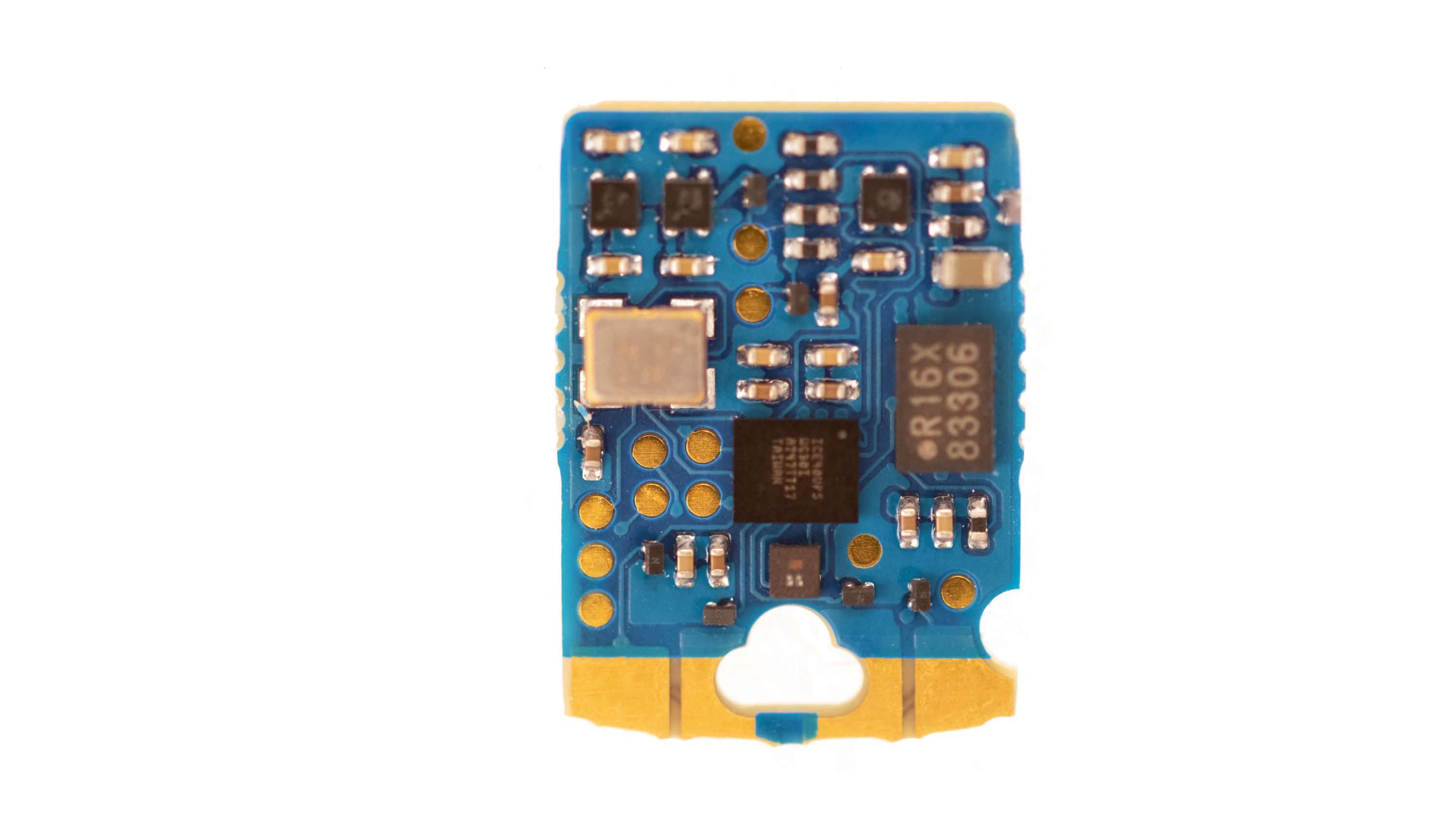
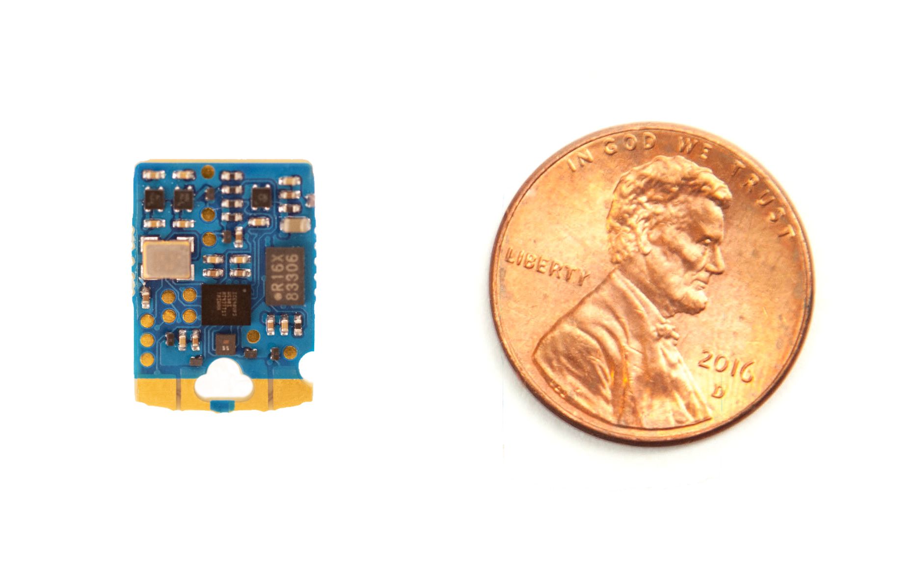
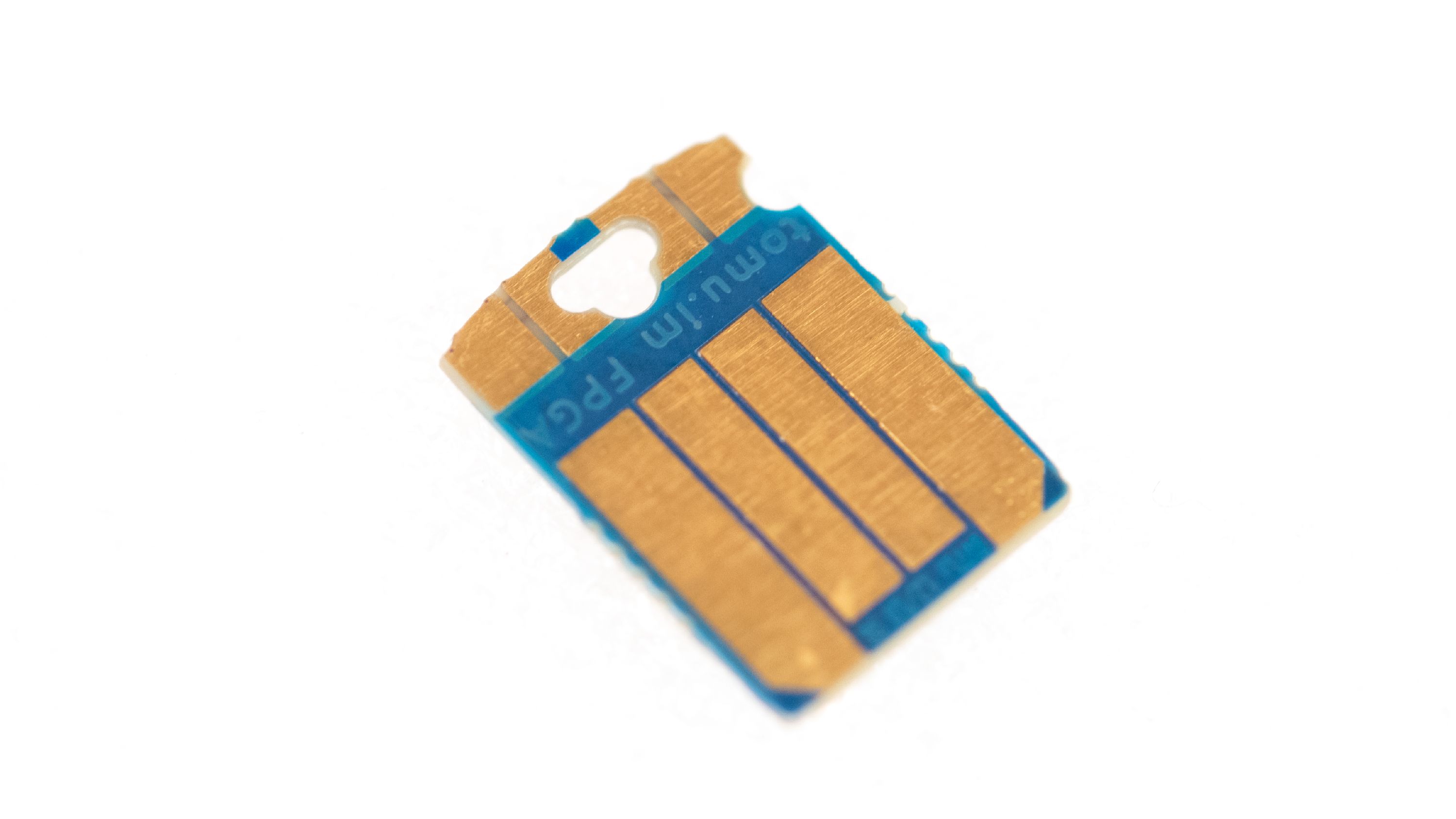
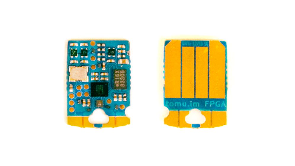
Fomu fits entirely inside a standard USB Type-A slot, except for a small area that pokes out to give you access to four copper pads. There is one RGB LED that lights up the case and is fully user-controllable. The main chip is an FPGA with about 5000 LUTs, enough for a CPU with some room left over.
¹: The FPGA has 1024 kilo-bits of memory available. A separate block of memory is used for things like the processor register file, in addition to temporary memory for things like USB buffers. The CPU can use 64 or 128 kilobytes of memory, depending on configuration.
²: This is the minimum configuration amount — more may be available in the final version.
³: Fomu has four copper pads near the edge. We have not yet validated any capacitive touch solutions.

| Fomu | Tomu | ICEBreaker | TinyFPGA BX | |
|---|---|---|---|---|
| Source | ||||
| PCB | Yes | Yes | Yes | Yes |
| Case | Yes | Yes | No | No |
| Bootloader | Yes | Yes | N/A | Yes |
| Physical | ||||
| Inputs | Four pads | Two pads | Four buttons | One reset |
| Outputs | One RGB LED | Two LEDs | Five LEDs | None |
| GPIO | None | None | 27 + 7 | 41 |
| Fits in USB port | Yes | Yes | No | No |
| USB interface | Softcore | Built-in | FTDI | Softcore |
| Specs | ||||
| Main chip | ICE40UP5K | EFM32HG309 | ICE40UP5K | ICE40LP8K |
| RAM | 128 kB | 8 kB | 128 kB | 16 kB |
| Flash | 2 MB | 64 kB | 16 MB | 1 MB |
| LUTs | 5280 | N/A | 5280 | 7680 |
| Clock | 48 MHz crystal | N/A | 12 MHz MEMS | 16 MHz MEMS |
Fomu is great for having convenient access to an FPGA that fits in your USB port. If you want a development board with lots of pins, you should check out one of the other ICE40 development boards available!
An FPGA is an Array of Gates that is Field-Programmable. When you buy a chip such as a CPU, the logic cells are all fixed in place. A CPU can run any amount of code, but if you want to do anything exotic you need to create software and, depending on what you want to do, that software can be very slow.
For example, many embedded projects use WS2812 LEDs such as NeoPixels that require a specialized timing signal. A CPU can generate this signal in software, but it can’t do anything in the background while talking to the light. If the string of LEDs is very long, then the CPU wastes a lot of time and power generating the signal.
With an FPGA, it becomes possible to create an "LED driver" that allows the CPU to keep running while a hardware component handles the timing. The CPU could do other work, or could put itself in a low power state.
In fact, the "CPU" in the FPGA is created from a hardware description language, meaning it can be modified or swapped out. If you wanted, you could create a brand-new CPU instruction. Do you want to have fast 64-bit multiplies? Or maybe you want a way to get random numbers easily? With Fomu and its FPGA, you have the source code to the CPU itself.

FPGAs are very specialized pieces of hardware, and, until recently, the development tools have been very closed. They usually require you to sign a non-disclosure agreement and then download a very, very large toolchain — usually well over 5 GB. Furthermore, because the toolchain was developed by the same company that sells FPGAs, they don’t have an incentive to make the synthesis efficient, because an inefficient toolchain means you must buy a larger FPGA, which earns them more money.
Thanks to several projects, the FPGA used in Fomu is fully open source. The company that makes the FPGA — Lattice — freely provides the datasheet and reference manual. And thanks to projects such as Yosys, IceStorm, and nextpnr, a fully open toolchain is now available.
This toolchain can be downloaded and shared freely, and each individual component is open source. This greatly simplifies setup, because you don’t have to create an account on the vendor’s site, sign an NDA, or set up a license server.
Fomu uses advanced, four-layer, blind-buried-via technology on the circuit board, which means it is difficult to manufacture in small quantities. In order to bring Fomu to the community, we have developed two versions of the PCB that are easier to manufacture:
The Hacker Version of Fomu was designed with 4/4 design rules on a two-layer PCB, and uses an unusual footprint for the main FPGA. Additionally, it uses a very particular SPI flash. These boards have been hand-assembled, but, due to the finicky nature of WLCSP balls, this board might not be reliable over the long term, and it may be extra susceptible to mechanical stress.
We won’t be selling any Hacker Version boards, but if you want to build your own Fomu and you’re comfortable with soldering very small components, you might give the Hacker Version a try.

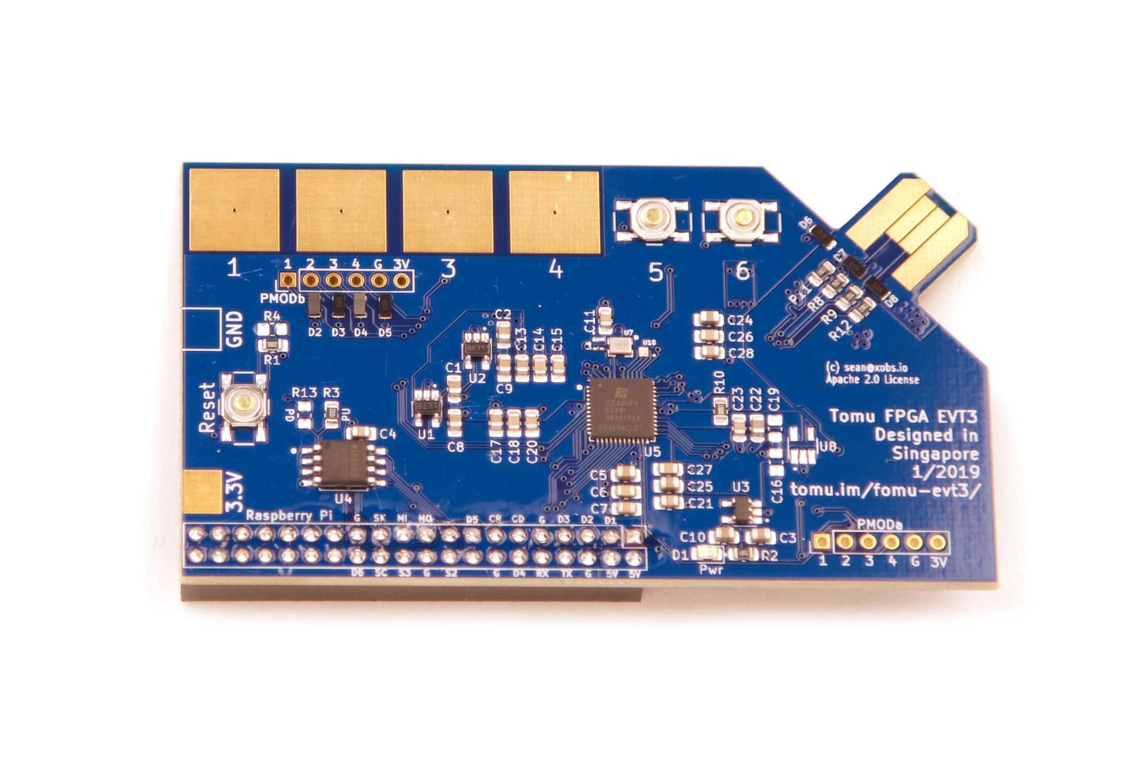
This is the first iteration of the modern version of Fomu. It is a "stretch" board, and was designed to test various assumptions such as SPI programming, crystal-versus-MEMS component selection, and regulator selection. It is designed to mate with a Raspberry Pi to allow for rapid application development and debugging.
A small number of these boards will be made available to interested customers, but we recommend users wanting full-sized FPGA boards consult TinyFPGA.
Fomu EVT was designed using 6/6 design rules on a standard two-layer PCB. It should be possible to produce at any PCB shop. Furthermore, while Fomu EVT includes many extra capacitors, most are not necessary, and may be removed to simplify assembly.
Fomu builds on the great Tomu community. Everyone loves having a computer in their USB port, and now they can have an FPGA in there as well.
We designed Fomu to be as open as possible. So, even if Fomu doesn’t quite do what you’d like out of the box, it’s possible to modify it to meet your needs:
These people helped out:
Without help from these people and countless others in the community, Fomu would not be possible at all. Thank you to everyone who has helped out so far.
We will manufacture Fomu in China.
One of the design goals of Tomu was to keep the part count low. Unfortunately, that was not possible with Fomu. This board has more components, and, as a result, those components will need to be smaller. To fit everything together, we will need to use a fancier PCB. Unlike Tomu, Fomu will require a crystal, external storage, and three separate voltage regulators, and FPGAs as a rule require a lot of decoupling capacitors. This increase in components means the design is more complex, so we will take a more rigorous approach to design.
Fomu is following a traditional three-cycle approach: Engineering, Design, and Production Validation and Testing, known as EVT, DVT, and PVT.
An EVT board makes sure that the schematic is correct, and generally doesn’t short out or get overly warm. An EVT board ensures that the pins do what you expect them to do, and allows you to evaluate the components and make good part choices.
A DVT board ensures the design is sound. This is where you shrink the board and make sure it can actually fit in the required space. You use DVT boards to design the case. There may be many changes in between EVT and DVT.

Finally, a PVT board is what you go to production with. Ideally, DVT and PVT are identical, but in practice there are usually a few changes. Maybe you increase the size of a cutout, or rearrange the pads slightly, as we did with Tomu. A PVT board is considered "done."
We have produced an EVT board. It is a stretch board, and is about the size of a business card. This board allows us to decide on components, such as which oscillator to use and how to arrange the voltage regulators. Additionally, this board is cheap to manufacture, and follows 6/6 rules so it can be produced at just about any PCB shop. The EVT board includes a Raspberry Pi header, which will make it easy to develop the bootloader firmware for Fomu.
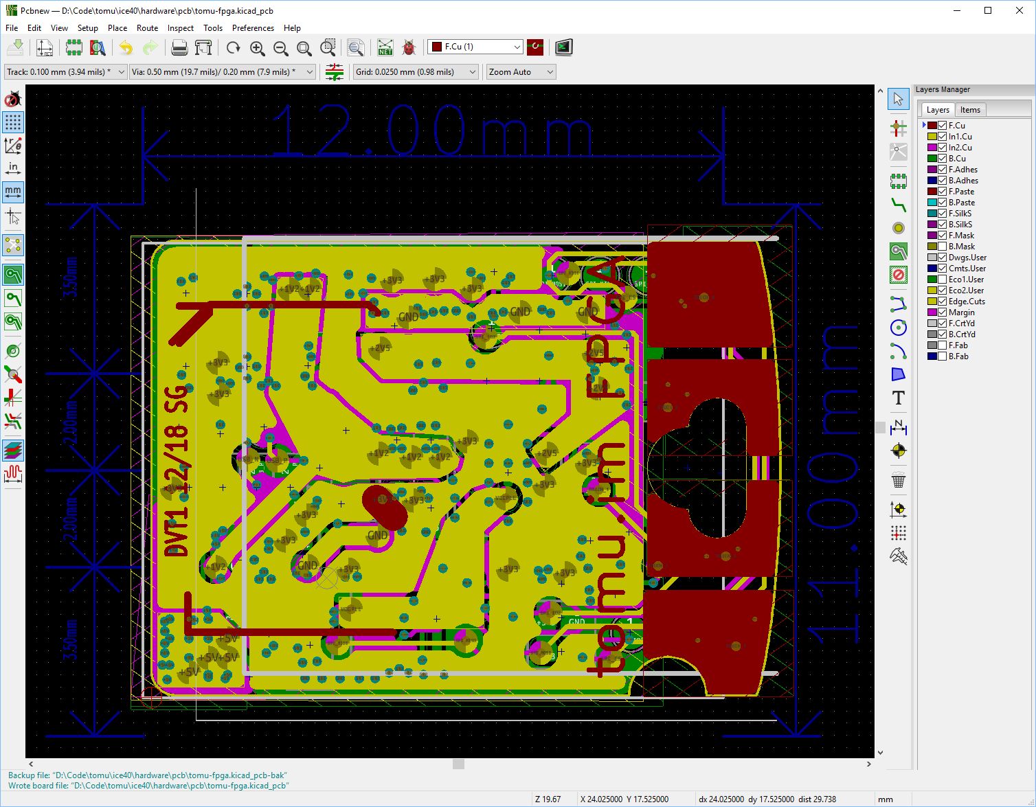
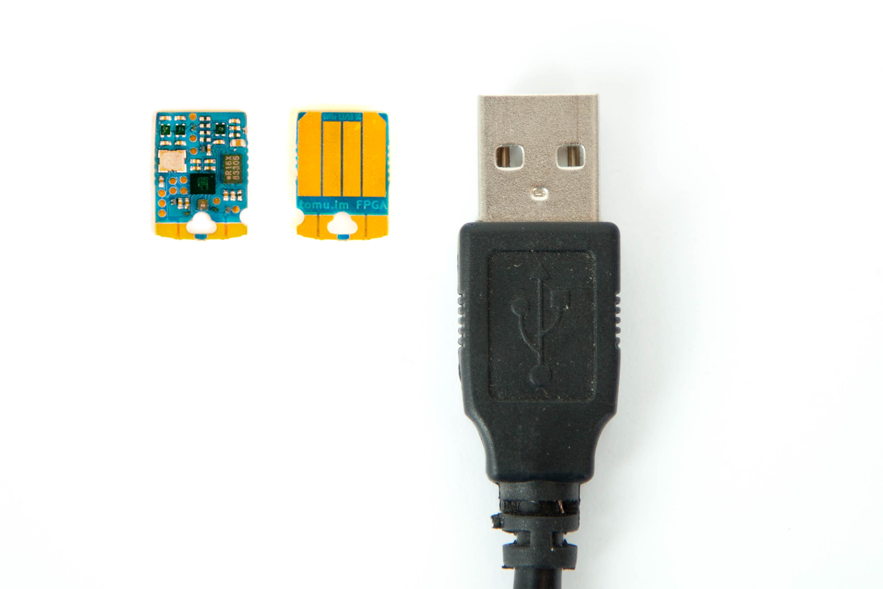
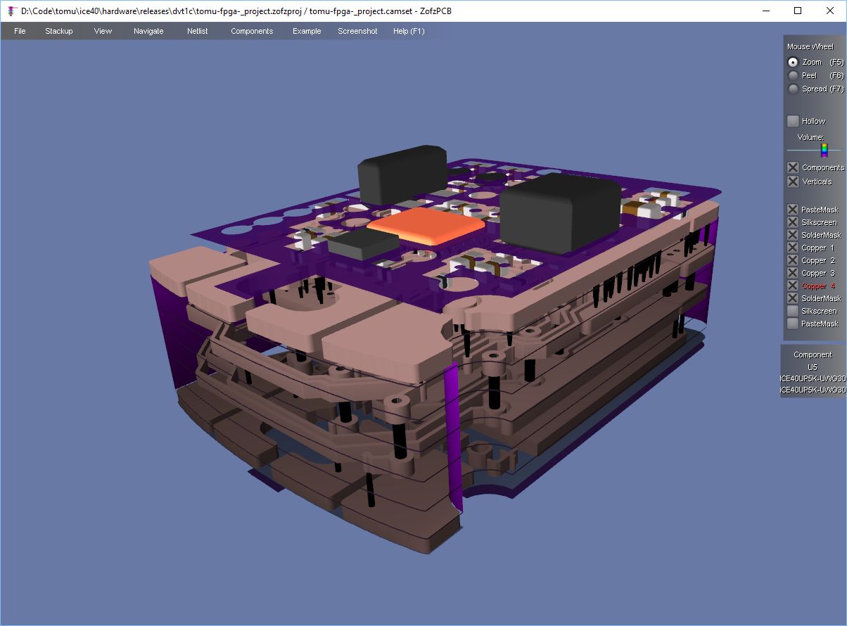
With the lessons learned from the EVT board, we have created a smaller DVT board. This includes most of the components from the EVT version, but shrinks it down to the size of a USB port. The DVT version must use a more complicated four-layer, blind-buried process, which allows for via connections between inner layers. We have also moved to the smaller ICE40 WLCSP component. Despite these mechanical changes, the schematic hasn’t changed much (e.g., components such as the Raspberry Pi header have been removed).
We will produce a small run of DVT boards in order to ensure the design is good. We will give some DVT boards to the plastics vendor to help redesign the Tomu case for the new arrangement of Fomu components. To make sure the bootloader design is good, we will also test DVT boards with as many USB ports as we can find. Once we’re happy with the DVT design, we’ll start production.
The actual production run will be called the PVT run. If the DVT run goes well, PVT will not change at all.

With Tomu, we managed to fund a plastic case. We will reuse most of the mold with Fomu. The PCB shape is slightly different, and with the addition of an RGB LED we will try to mold a light pipe into the shape of the case. That way, the entire plastic shell will light up inside the USB port.
The plastic mold itself should require only minor modifications, and will be relatively inexpensive to change. However, the plastics factory really likes to work with physical goods, and so we will need to supply them with a DVT board for them to measure and shape. Once they have the DVT board, they can set to work etching steel for the tool and running the tests required to mate plastic with electronics.
The Fomu printed circuit board — the PCB — will need to be much more complicated than a traditional PCB. The FPGA chip itself is in a very tiny package called a Wafer-Level Chip-Scale Package (WLCSP), which is a super small rectangle with an array of balls underneath. In order to reliably use this chip, we will need to use a fancy multi-stage PCB manufacturing process known as blind-buried vias.
Normally, when you build a circuit board you make a sandwich of materials including fibreglass and copper, etch away the copper, drill holes, electroplate it, and then add a mask layer and some silkscreen.
With a blind-buried board, you do all of that, and then you add more material to the sandwich, line up the boards properly, and laser-drill the additional layers. Then you mechanically drill any through-holes and cut out the finished PCB. This process is very complicated and is difficult to do cheaply in small quantities.
We have found a PCB factory that can work with our volumes, and the DVT revision of the main PCB will be the first built using these extra-small design rules.

"Capable of running a soft RISC-V core, it is completely compatible with FμPy which is a MicroPython port to run on FPGA using Migen+MiSoC and LiteX, allowing FPGA gateware and soft CPU firmware development in Python."
"You could practice adding peripherals to RISC-V and other cores, but maybe what you should be thinking is: what could I do with my laptop if I had some dedicated parallel processing available?"
Produced by Sutajio Kosagi in Singapore.
Sold and shipped by Crowd Supply.

An FPGA for your USB port! Includes one pre-flashed Fomu and a plastic case.

An EVT board revision is used to validate the schematic is correct, and to help develop the software. This EVT board is what we'll use to develop the USB stack and to make sure we've got the power and other hardware parts wired up right. Designed to mount onto a Raspberry Pi to upload a bitstream and debug the CPU.This is a limited-time production board, and won't be produced after the few remaining sell.
Sutajio Ko-usagi supports and produces open hardware products designed by bunnie and xobs.